
 WhatsApp: +86 16626708626
 Email:
  Phone: +86 16626708626
Description
Key Technical Specifications
| Parameter | Specification |
|---|---|
| Model | RRDIO15 |
| Manufacturer / OEM Association | Rolls-Royce Marine |
| Hardware Manufacturer | Weidmüller, according to Radwell |
| Product Type | I/O Alarm Module |
| Channel Count | 15 channels |
| Signal Type | Digital I/O |
| Primary Function | Signal acquisition, control outputs, and alarm processing |
| Application | Marine automation and shipboard equipment monitoring |
| System | Rolls-Royce Marine CANMAN |
| Typical Signal Sources | Equipment status, switches, valve positions, alarm contacts |
| Output Role | Digital control and alarm-related outputs |
| Communication Interface | Verify against the installed CANMAN system |
| Supply Voltage | Verify from the equipment documentation and nameplate |
| I/O Electrical Levels | Verify against the installed system configuration |
| Mounting Arrangement | Verify from the physical module and vessel drawings |
| Manufacturer Status | Discontinued according to Radwell |
The strongest available identification describes RRDIO15 as a 15-channel Rolls-Royce Marine I/O alarm module and associates it with Weidmüller hardware.
Some aftermarket sources publish substantially different specifications, including 24 VDC operation, CAN-bus communication, DIN-rail mounting, 16-channel operation, and specific environmental ratings. Because these claims conflict with the more conservative 15-channel identification, they should not be treated as verified specifications for every RRDIO15 unit. Match the physical module, terminal arrangement, system drawings, and original documentation before replacement.
Product Introduction
The Rolls-Royce RRDIO15 is a legacy marine I/O alarm module used to interface digital field signals with shipboard automation and alarm systems. Current marine-spares records associate the module with the Rolls-Royce Marine CANMAN architecture and identify it as a 15-channel I/O alarm card. Typical applications include monitoring equipment status and transferring discrete alarm or control signals between field equipment and the vessel’s automation system.
For maintenance teams, the RRDIO15 is primarily an exact-replacement component rather than a generic digital I/O module. The installed vessel configuration determines its signal assignments, communication arrangement, and electrical characteristics. This makes the complete part number, physical hardware, terminal configuration, and vessel drawings important when sourcing a replacement.
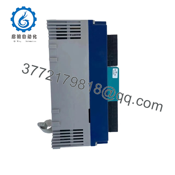
RRDIO15
Installation & Configuration Guide
Stage 1 — Pre-Installation Preparation
Estimated time: 30–60 minutes, excluding vessel-specific isolation and commissioning.
- Identify the vessel automation system and confirm that RRDIO15 is the installed I/O module.
- Review the vessel’s electrical drawings, I/O list, and CANMAN documentation.
- Place the affected automation system into the approved maintenance condition.
- Apply the vessel’s lockout/tagout and electrical isolation procedure.
- Prevent remote control stations from issuing unintended commands.
- Record active alarms and I/O states before removing the module.
- Photograph the existing and all terminal connections.
- Record the complete module identification and hardware revision.
- Prepare ESD protection before handling the electronic assembly.
- Compare the replacement unit with the existing module before disconnecting it.
⚠️ Do not assume the supply voltage or communication interface from an online product listing. Available aftermarket records contain conflicting technical data. Verify the vessel documentation and the actual module markings before applying power.
Stage 2 — Removing the Old Module
- Confirm that all affected equipment is in a safe operating state.
- Isolate the module’s electrical supply.
- Verify the absence of hazardous voltage using an appropriately rated meter.
- Label every wire and terminal before disconnecting it.
- Photograph the terminal arrangement from multiple angles.
- Disconnect communication and I/O connections without pulling individual conductors.
- Release the module from its mounting arrangement according to the original equipment design.
- Remove the and place it on an ESD-safe surface.
- Inspect the terminal blocks, connectors, and surrounding wiring for:
- Corrosion
- Loose terminals
- Moisture or salt contamination
- Bent contacts
- Damaged insulation
- Overheating or discoloration
- Retain the removed module until the replacement has passed commissioning.
Stage 3 — Installing the New Module
- Verify the replacement is marked .
- Compare the physical layout and terminal configuration with the removed module.
- Confirm the hardware revision where applicable.
- Verify the I/O channel arrangement against the vessel I/O list.
- Inspect all connectors and terminals before installation.
- Install the module using the original mounting arrangement.
- Reconnect field wiring according to the vessel drawings and installation photographs.
- Reconnect the communication/system-bus connection if fitted.
- Check every terminal for secure mechanical retention.
- Verify shielding and grounding arrangements according to the original installation.
- Check that no conductors are loose, pinched, or under mechanical stress.
- Do not change I/O assignments simply to accommodate a replacement module.
⚠️ should not be substituted with another digital I/O module merely because it has a similar channel count. The vessel’s control software, signal mapping, electrical interface, and communication architecture must all be compatible.
Stage 4 — Power-On & Testing
- Perform a final wiring inspection.
- Confirm that all personnel are clear of affected machinery.
- Restore power according to the approved vessel procedure.
- Check module status indicators, if fitted.
- Verify communication with the central marine automation system.
- Check for module diagnostics or communication alarms.
- Confirm each connected digital input changes state correctly.
- Verify the corresponding alarm or status indication at the operator station.
- Test applicable digital outputs under controlled conditions.
- Confirm that output commands operate the intended equipment.
- Verify alarm acknowledgement and reset behavior where applicable.
- Compare the final I/O status against the vessel’s approved I/O list.
- Record the replacement part number, hardware revision, test results, and remaining alarms.
⚠️ Do not use forced I/O states as a substitute for a complete commissioning test. Any temporary force or bypass used for troubleshooting must be removed and documented before the system returns to normal service.
Frequently Asked Questions (FAQ)
What is the Rolls-Royce ?
is identified in current industrial records as a 15-channel I/O alarm module for Rolls-Royce Marine systems. Radwell’s listing identifies the hardware manufacturer as Weidmüller and describes it as a Rolls-Royce Marine card.
Is a digital input/output module?
Yes. Its documented role is an I/O alarm module handling digital field signals associated with marine automation and alarm functions. Supplier records describe applications involving equipment status monitoring and alarm/control signals.
Is discontinued?
Yes. Radwell currently identifies as discontinued by the manufacturer. Aftermarket sources continue to list unused and refurbished units.
Is hot-swappable?
Do not assume that it is hot-swappable. The available documentation does not establish a universal hot-swap procedure for all installations. Treat module replacement as a powered-down maintenance activity unless the vessel-specific Rolls-Royce documentation explicitly permits live replacement.
Does operate on 24 VDC?
Some aftermarket listings claim 24 VDC operation, while other records do not provide a verified electrical supply specification. Therefore, 24 VDC should not be used as a procurement or installation assumption without checking the actual module documentation and vessel wiring diagram.
Is compatible with any Rolls-Royce Marine automation system?
No. Compatibility depends on the specific vessel automation architecture, I/O mapping, hardware revision, communication arrangement, and software configuration. Match the complete system context rather than the model number alone.
What condition should I specify when sourcing ?
Specify the required condition explicitly: New Original / New Surplus, Unused Original Packaging, or Refurbished and tested. These conditions are not equivalent. Radwell currently lists unused and refurbished condition categories for the discontinued part.
What information should I provide when ordering a replacement?
Provide the complete part number, photographs of the existing module, hardware revision, terminal layout, vessel automation system, I/O channel assignment, and any active alarm or communication diagnostic. This information helps distinguish the Rolls-Royce Marine from unrelated products that happen to use the same part number.



