
 WhatsApp: +86 16626708626
 Email:
  Phone: +86 16626708626
Description
Key Technical Specifications
| Parameter | Specification |
|---|---|
| Manufacturer | Rolls-Royce Marine |
| Model | SLIO 01 |
| System | CANMAN |
| Full Functional Description | Serial Linked I/O node |
| Network | CAN-based local I/O bus |
| Analog Inputs | 6 channels |
| AI Channels 0–1 | 4–20 mA active |
| AI Channels 2–5 | 0.5–4.5 V |
| Analog Outputs | 1 channel |
| AO Type | 4–20 mA source |
| Digital I/O | Supported; channel allocation depends on application |
| Signal Calibration | CANMAN software/HHT calibration |
| Primary Applications | Propulsion, thruster, engine and vessel automation |
| Approx. Weight | 0.600 kg |
| Supply Voltage | Verify against the installed CANMAN documentation |
| Physical Mounting | Verify against the original vessel installation |
| Hardware Revision | Verify from the module label |
The Rolls-Royce CANMAN documentation identifies SLIO01 as a Serial Linked I/O type. It distinguishes SLIO01 from SLIO02 by I/O configuration. The documentation specifies six analog input channels for SLIO01: channels 0 and 1 can be configured for active 4–20 mA, while channels 2 through 5 can be configured for 0.5–4.5 V. The single analog output supports 4–20 mA source operation.
Current supplier records also identify SLIO 01 as a Rolls-Royce CANMAN I/O module and report an approximate weight of 0.6 kg.
Product Introduction
The Rolls-Royce SLIO 01 is a Serial Linked I/O module used within the CANMAN marine control architecture. It functions as a distributed I/O node, transferring field signals between propulsion or vessel equipment and the CANMAN controller. NTSB documentation describing a CANMAN installation confirms that SLIO cards provide analog and digital inputs and outputs, with different SLIO types using different I/O configurations.
The SLIO 01 is particularly relevant to legacy Rolls-Royce marine propulsion and thruster systems where individual field signals must be acquired and calibrated at the local I/O level. Its documented analog configuration includes active 4–20 mA inputs, 0.5–4.5 V inputs, and a 4–20 mA source output.
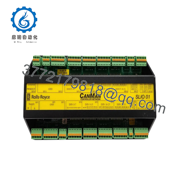
SLIO 01
Installation & Configuration Guide
Stage 1 — Pre-Installation Preparation
Estimated time: 30–60 minutes, excluding vessel-specific shutdown and commissioning.
- Identify the CANMAN controller and the exact SLIO 01 node being replaced.
- Review the vessel’s I/O list and CANMAN configuration.
- Record the SLIO node number, application assignment, and existing calibration values.
- Place the affected propulsion or vessel-control system in the approved maintenance state.
- Apply the vessel’s lockout/tagout and electrical isolation procedure.
- Prevent bridge, local, and remote control stations from issuing unintended commands.
- Photograph the SLIO 01 and all field wiring before removal.
- Label every I/O conductor and communication connection.
- Record the module’s hardware revision and identification markings.
- Prepare ESD protection before handling the module.
⚠️ Do not substitute signal types during installation. For SLIO01, the CANMAN documentation distinguishes active 4–20 mA inputs, 0.5–4.5 V inputs, and a 4–20 mA source output. Connecting a transmitter with a different electrical interface without confirming compatibility can produce incorrect process values or damage the I/O circuitry.
Stage 2 — Removing the Old Module
- Confirm that the affected equipment is in a safe maintenance state.
- Isolate the SLIO 01 power supply according to the vessel procedure.
- Verify electrical isolation with an appropriately rated meter.
- Label every field terminal before disconnecting it.
- Photograph the terminal arrangement.
- Disconnect the CANMAN/S-Bus connection where fitted.
- Disconnect the field I/O wiring.
- Release the module from its original mounting arrangement.
- Remove the SLIO 01 and place it on an ESD-safe surface.
- Inspect the wiring and terminals for:
- Corrosion
- Loose connections
- Moisture or salt contamination
- Damaged insulation
- Bent contacts
- Overheating
- Retain the removed module until commissioning is complete.
Stage 3 — Installing the New Module
- Confirm the replacement is SLIO 01, not SLIO 02 or another CANMAN I/O type.
- Compare the physical module and terminal arrangement with the removed unit.
- Verify the hardware revision where applicable.
- Install the replacement in the original mounting position.
- Reconnect the CANMAN communication wiring.
- Reconnect every field I/O conductor according to the vessel drawings.
- Verify polarity for analog signals.
- Confirm that active 4–20 mA transmitters are connected only to the appropriate SLIO01 input channels.
- Confirm 0.5–4.5 V signals are connected to the channels configured for that signal type.
- Verify the 4–20 mA output loop wiring before energizing the module.
- Check every terminal for secure mechanical retention.
- Confirm shielding and grounding arrangements against the original installation.
⚠️ Do not assume SLIO01 and SLIO02 are interchangeable. CANMAN documentation specifies different analog signal capabilities for the two module types.
Stage 4 — Power-On & Testing
- Perform a final wiring inspection.
- Restore power according to the approved vessel procedure.
- Confirm that the CANMAN system detects the SLIO node.
- Check for CANMAN communication or I/O diagnostics.
- Verify digital input states against known field conditions.
- Verify digital output operation under controlled conditions.
- Check each analog input against a calibrated reference or known process value.
- Confirm channels 0–1 correctly read the intended active 4–20 mA signals.
- Confirm channels 2–5 correctly read the intended 0.5–4.5 V signals.
- Verify the 4–20 mA output against the configured process value.
- Perform CANMAN calibration where required.
- Record the final calibration values and I/O status.
- Verify alarms and control interlocks before returning the vessel system to normal operation.
The CANMAN service documentation provides dedicated calibration procedures for SLIO analog inputs and outputs, including high, low, and zero calibration points where applicable.
Frequently Asked Questions (FAQ)
What is the Rolls-Royce SLIO 01?
SLIO 01 is a Serial Linked I/O module used in the Rolls-Royce CANMAN marine control system. It provides distributed analog and digital I/O between field equipment and the CANMAN controller.
What analog inputs does SLIO 01 support?
According to CANMAN documentation, channels 0 and 1 support active 4–20 mA inputs. Channels 2 through 5 support 0.5–4.5 V inputs.
Does SLIO 01 have an analog output?
Yes. The CANMAN documentation identifies one analog output on , configurable as a 4–20 mA source.
Is SLIO 01 the same as SLIO 02?
No. They are different CANMAN SLIO types with different I/O configurations. The documentation specifically lists different analog signal capabilities for and SLIO02.
Can SLIO 01 be hot-swapped?
Do not assume hot-swap capability. The available CANMAN documentation does not establish a universal hot-swap procedure for . Unless the vessel-specific documentation explicitly permits live replacement, perform the replacement with the affected system safely isolated.
Does replacing SLIO 01 require calibration?
It can. CANMAN documentation provides calibration procedures for analog inputs and outputs, including calibration points used to correlate electrical signals with displayed process values. Existing calibration data should be recorded before replacement and restored or re-established during commissioning.
What condition is normally available?
Aftermarket listings include used and other surplus conditions. One current supplier lists SLIO 01 as used at approximately 0.600 kg. Condition, testing, warranty, and configuration should be confirmed for the specific unit before purchase.
What should I provide when sourcing a replacement?
Provide the exact SLIO 01 identification, module photographs, hardware revision, CANMAN node number, vessel/control-system information, I/O channel assignment, and any existing alarm or communication fault. For this legacy marine module, matching the I/O configuration is as important as matching the model name.



