
 WhatsApp: +86 16626708626
 Email:
  Phone: +86 16626708626
Description
Key Technical Specifications
| Parameter | Specification |
|---|---|
| Manufacturer | Rolls-Royce Marine |
| Model | WRC1021D |
| Item ID | 000070089 |
| Product Type | Remote Controller / Valve Controller PCB |
| Application | Marine deck machinery and hydraulic valve control |
| Supply Voltage | 230 VAC, 50–60 Hz; 24 VDC |
| 230 VAC Consumption | 0.04 A with no servo valves connected |
| 24 VDC Consumption | 4.0 A maximum, depending on output-limit alarms |
| Servo Driver Output | 1.5 A maximum at 220 VAC |
| Limit Alarm Output | 2.0 A maximum at 24 VDC |
| Board Dimensions | 100 × 160 mm |
| Board Format | Euro Card |
| Board Weight | 385 g |
| Control Principle | Order/feedback signal comparison |
| Adjustment Functions | Position, speed, limits and alarm settings |
| Construction | SMD technology |
| Replacement Role | Replacement for older WRC1021 boards |
| Serial Identification | Serial number and product revision number assigned to individual boards |
The available WRC1021D instruction document provides the strongest technical reference for the electrical ratings and physical format. It identifies WRC1021D as a replacement for the older WRC1021 board and states that the newer design is mechanically and functionally compatible.
The same documentation describes a servo-control architecture in which the controller compares an order signal with feedback and drives the associated servo valve accordingly. Potentiometers and switches are provided for calibration of limits, positions, speeds and alarms.
Product Introduction
The Rolls-Royce Marine WRC1021D is a remote valve controller PCB designed for marine deck-machinery applications. It compares command and feedback signals and controls servo-valve outputs for functions such as hoisting, lowering and bypass operation. The board is built in a 100 × 160 mm Euro Card format and uses SMD technology.
The WRC1021D was designed as a replacement for earlier WRC1021 boards while maintaining mechanical and functional compatibility. Its dual supply arrangement supports 230 VAC and 24 VDC system requirements, while the board provides dedicated servo-driver and limit-alarm outputs. Individual boards carry serial and revision identification, which should be checked when sourcing a replacement.
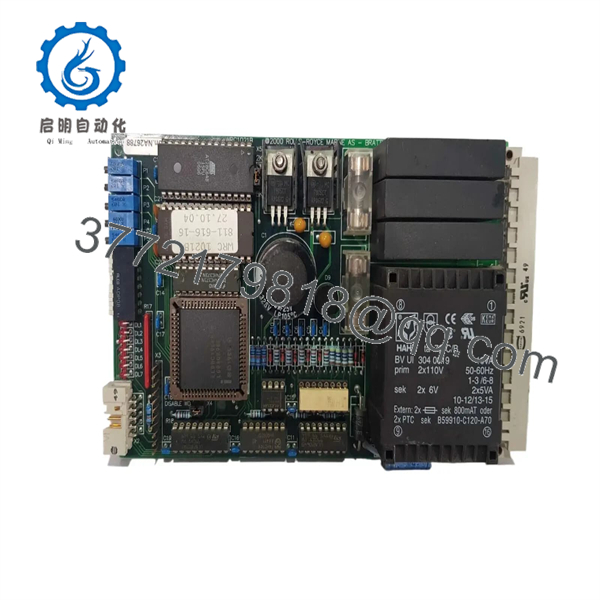
WRC1021D
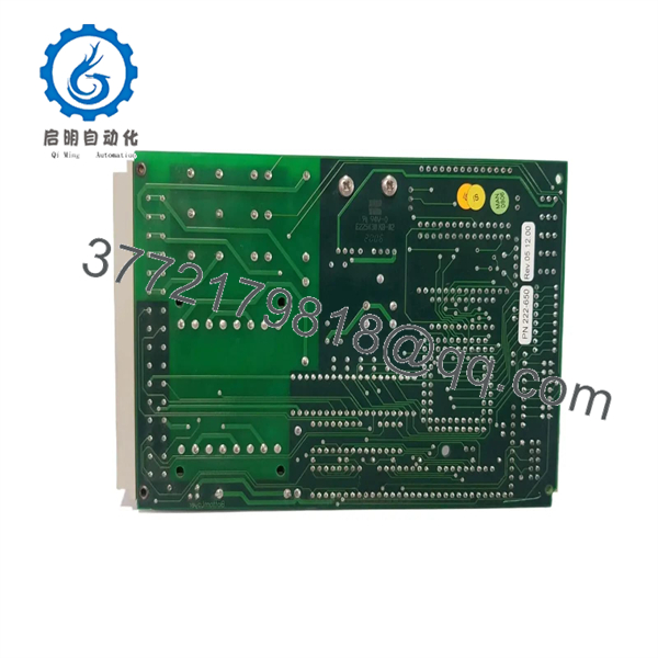
WRC1021D
Installation & Configuration Guide
Stage 1 — Pre-Installation Preparation
Estimated time: 30–60 minutes for board replacement, excluding hydraulic-system commissioning.
- Identify the exact WRC1021D revision and serial number.
- Review the deck-machinery electrical drawings and hydraulic-control documentation.
- Place the winch, hoist, or associated deck machinery into the approved maintenance condition.
- Apply lockout/tagout (LOTO) to electrical and hydraulic energy sources.
- Confirm that remote and local controls cannot generate an unintended movement command.
- Depressurize the hydraulic circuit according to the vessel’s maintenance procedure where required.
- Record existing potentiometer settings before removing the board.
- Photograph all wiring and connector positions.
- Label every wire before disconnecting it.
- Prepare ESD protection before handling the PCB.
⚠️ The controls physical hydraulic equipment. Do not begin electrical testing while the connected winch, hoist, or valve actuator can move unexpectedly.
Stage 2 — Removing the Old Module
- Confirm electrical and hydraulic isolation.
- Verify the absence of hazardous electrical voltage.
- Record the existing adjustment-potentiometer positions.
- Label all field wiring and servo-valve connections.
- Photograph the complete board installation.
- Disconnect the power supply.
- Disconnect the servo-valve and limit-alarm wiring.
- Release the Euro Card from its rack or mounting arrangement.
- Remove the existing controller carefully.
- Inspect the card connector, socket, wiring and cabinet for:
- Corrosion
- Loose contacts
- Moisture or salt contamination
- Burn marks
- Damaged conductors
- Mechanical damage
- Keep the removed WRC1021/ until commissioning is complete.
Stage 3 — Installing the New Module
- Confirm the replacement is .
- Check the board serial number and revision identification.
- Compare the connector layout with the removed controller.
- Confirm that the replacement uses the correct 100 × 160 mm Euro Card interface.
- Install the board into the correct rack position.
- Reconnect the power wiring according to the approved schematic.
- Reconnect servo-valve outputs.
- Reconnect limit and alarm circuits.
- Verify polarity and terminal assignments.
- Confirm that no wire is loose or mechanically stressed.
- Recheck every connection before energizing the system.
- Restore the recorded potentiometer settings as an initial reference only.
⚠️ Do not treat the original potentiometer positions as a guaranteed calibration. Mechanical wear, valve characteristics, feedback-potentiometer position and hydraulic conditions can change the required adjustment.
Stage 4 — Power-On & Testing
- Complete a final electrical and mechanical inspection.
- Confirm that the hydraulic system remains in a safe commissioning condition.
- Apply the appropriate control power.
- Check the board’s status indicators.
- Verify the command/order signal.
- Verify the feedback signal from the controlled mechanism.
- Test servo-valve output with the machinery secured.
- Check limit-switch and alarm circuits.
- Perform the calibration procedure using the applicable service instructions.
- Adjust position limits and speed settings as required.
- Verify hoist, lower and bypass functions independently.
- Confirm correct response to the feedback signal.
- Perform a controlled operational test at low risk before returning the equipment to normal service.
- Record final adjustment settings and board serial/revision information.
The documentation includes dedicated sections covering calibration, feedback potentiometers, servo-system operation, errors and troubleshooting.
Frequently Asked Questions (FAQ)
What is the Rolls-Royce ?
The is a marine remote valve controller PCB used to compare command and feedback signals and control servo-valve functions. Its documented applications include hoist, lower and bypass functions in deck machinery.
Is compatible with the older WRC1021?
Yes. The available instruction document explicitly states that the replaces the older WRC1021 and is mechanically and functionally compatible with it.
What power supply does use?
The documented supply options are 230 VAC at 50–60 Hz and 24 VDC. The documentation specifies approximately 0.04 A at 220 VAC with no servo valves connected and up to 4.0 A at 24 VDC depending on output-limit alarms.
What is the servo-valve output rating?
The documented maximum servo-driver output is 1.5 A at 220 VAC. The maximum limit-alarm output is 2.0 A at 24 VDC. These are maximum ratings, not recommended operating values for every connected valve or alarm circuit.
What are the physical dimensions of ?
The board uses a 100 × 160 mm Euro Card format and weighs approximately 385 g.
Does require calibration after replacement?
Yes, calibration should be treated as part of commissioning. The controller uses adjustable settings for limits, position, speed and alarms, and its feedback signal is part of the servo-control loop. Record the old settings before replacement, then verify them under controlled operating conditions.
Can I install without checking the serial or revision number?
It is not advisable. The manufacturer documentation states that boards carry a serial number and product revision number. Check these against the existing system and procurement requirements before installation.
What condition should I specify when sourcing ?
Specify the exact condition required, such as New Original / New Surplus, Factory Sealed, or Refurbished and tested. Do not accept a generic “new” description without confirming whether the board is original, surplus, refurbished, or previously installed.
What should I provide when sourcing a replacement ?
Provide , the board serial/revision information, photographs of the existing card, the associated winch or hydraulic system, supply arrangement, servo-valve details, and any existing fault symptoms. This information helps verify the correct board and calibration requirements.



