
 WhatsApp: +86 16626708626
 Email:
  Phone: +86 16626708626
Description
Key Technical Specifications
| Parameter | Value |
|---|---|
| Model / Part Number | BG02.510 |
| Brand | Safetec |
| System | SDS-48 Smoke Detection System |
| Product Type | Control Module for Repeater Panel |
| Primary Function | Repeater-panel system operation and indication |
| Display | LC display |
| Status Indication | LED indicators |
| Operator Interface | Push button |
| Mounting Location | Behind the front cover of the repeater panel |
| Dimensions | 182 × 105 × 38 mm |
| Weight | 270 g |
| Associated Panel | Safetec SDS-48 repeater panel |
| Related Repeater System | SDS02.300 / SDS02.301 repeater panels |
| Supply Voltage | Not specified for the BG02.510 module itself; verify system documentation |
| Communication Protocol | Not specified in the available product documentation |
| Firmware Version | Not specified; verify the installed system revision before replacement |
Safetec’s product documentation specifies the 182 × 105 × 38 mm dimensions and 270 g weight. It also identifies the LC display, LEDs, and push button as integral functions of the module.
Product Introduction
The Safetec BG02.510 is a control module installed behind the front cover of the repeater panel used with the SDS-48 smoke detection system. It provides the LC display, LED indication, and push-button interface required for local operation and status observation.
The module is a dedicated SDS-48 repeater-panel component rather than a general-purpose PLC or I/O module. Its documented dimensions are 182 × 105 × 38 mm with a mass of 270 g. Verify the exact repeater-panel version and existing module markings before replacement.
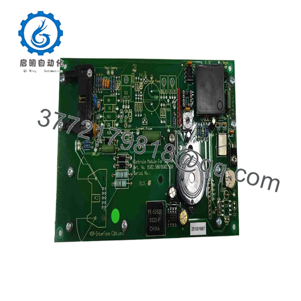
BG02.510
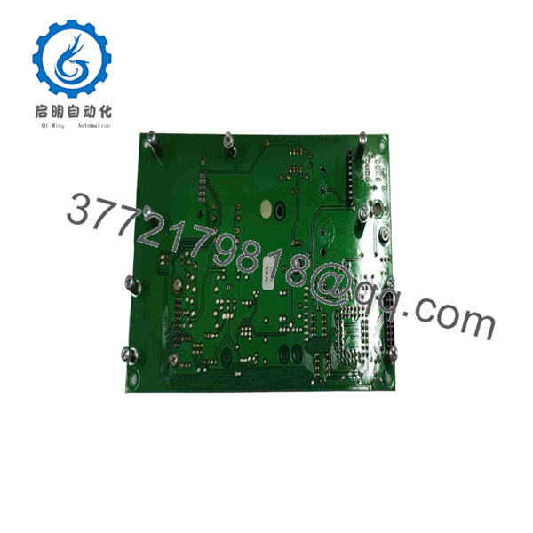
BG02.510
Installation & Configuration Guide
Stage 1: Pre-Installation Preparation — Approximately 5–10 Minutes
⚠️ Safety First: The SDS-48 is part of a smoke detection and safety system. Place the affected system in the appropriate maintenance state according to the vessel or plant safety procedure before removing the module. Do not bypass active fire-protection functions without authorization.
- Notify operations and establish the approved maintenance window.
- Isolate power according to the applicable lockout/tagout procedure.
- Allow sufficient time for stored electrical energy to dissipate before opening the panel.
- Confirm that the replacement is marked BG02.510.
- Compare the physical replacement with the installed module before disconnecting anything.
Tools Required
- ESD wrist strap
- Insulated screwdriver appropriate for the installed fasteners
- Digital multimeter
- Wire labels
- Smartphone or camera for documentation
- SDS-48 documentation and wiring drawings
Data Backup / Documentation
Before removing the old module:
- Photograph the complete repeater-panel assembly.
- Photograph every connector and terminal position.
- Record all visible module identification markings.
- Record the system configuration and alarm status.
- Photograph any jumpers, switches, connectors, or configuration components present on the installed revision.
⚠️ Do not assume that a replacement module has identical configuration settings simply because the part number matches. Compare the actual hardware revision and panel configuration.
Stage 2: Removing the Old Module — Approximately 5 Minutes
- Confirm the system is in the approved maintenance state.
- Isolate the relevant electrical supply.
- Remove the repeater-panel front cover or bezel according to the mechanical arrangement.
- Photograph the installed BG02.510 before disturbing any connections.
- Label each connector or wire before removal.
- Disconnect the module carefully. Do not pull on individual conductors.
- Release the module’s mechanical retaining hardware.
- Remove the control module without forcing the PCB or connector.
- Inspect the connector, mounting area, and wiring for contamination, corrosion, bent contacts, or mechanical damage.
The BG02.510 is documented as being mounted behind the front cover of the repeater panel, so access is primarily through the repeater-panel front assembly rather than through the main power-supply section.
⚠️ Keep the original module on site until commissioning is complete. It remains the most useful physical reference if a connector position or hardware revision becomes unclear.
Stage 3: Installing the New Module — Approximately 5–10 Minutes
- Put on the grounded ESD wrist strap before handling the replacement PCB.
- Verify the marking against the removed module.
- Compare connector orientation and mechanical dimensions.
- Compare the PCB revision and visible configuration components.
- Replicate documented configuration settings exactly where applicable.
- Install the module in the repeater-panel mounting position.
- Ensure the module seats correctly without excessive mechanical force.
- Reconnect each connector using the photographs and wiring labels as references.
- Check that connectors are fully seated.
- Reinstall the front cover or bezel.
Replacement Self-Checklist
- .510 part number verified
- Hardware revision compared
- Connectors match the original positions
- Configuration components checked
- Wiring secured
- Module mechanically secured
- No PCB damage or bent contacts
- Front cover correctly refitted
Stage 4: Power-On & Testing — Approximately 10 Minutes
- Perform a final visual inspection before energizing the system.
- Verify there are no loose conductors or unintended shorts.
- Restore power according to the operating procedure.
- Observe the LC display and LED indicators during startup.
- Confirm that the repeater panel reaches its normal operating state.
- Operate the applicable push-button functions.
- Verify that displayed system status agrees with the main panel.
- Confirm that normal smoke-detection indications are available at the repeater panel.
- Test applicable alarm/fault indications using the approved test procedure.
- Record the replacement date, module identification, observed indications, and test result.
⚠️ Do not manufacture a firmware or communication diagnosis for this module. Available documentation identifies the .510 as a dedicated repeater control module but does not provide a firmware revision or standard Ethernet/Profibus/Modbus interface specification.
If the replacement does not operate correctly, first check connector seating, module revision, panel compatibility, power availability, and the system fault indication. Do not immediately assume the module itself is defective.
Frequently Asked Questions (FAQ)
Q1. What is the Safetec .510?
The .510 is the control module for the repeater panel in the Safetec smoke detection system. It contains the LC display, LED indicators, and push button used for repeater-panel operation.
Q2. Is .510 the same as the .500?
No. They have different functions. is the control module for the main smoke detection panel, while is the control module for the repeater panel. The spare-parts documentation lists them as separate components.
Q3. Can I hot-swap the .510?
Do not assume that it is hot-swappable. The available documentation does not establish a hot-swap procedure for .510. For a fire-detection system, isolate the relevant power and place the system into its approved maintenance state before removing the module.
Q4. Is .510 obsolete?
The .510 belongs to the established Safetec product family, and current spare-parts listings still identify it as the repeater control module. However, the age of the documentation means stock condition and production status should be verified for each unit.
Q5. Does replacing .510 erase the system configuration?
The available documentation does not indicate that .510 stores the complete system configuration. It is described primarily as the repeater-panel control module containing the display, LEDs, and push button. Nevertheless, photograph the existing installation and preserve the original module until commissioning is complete.
Q6. What condition should I specify when ordering .510?
Specify the required condition explicitly: New Original / New Surplus, Factory Sealed, or Refurbished and Tested. Do not accept a generic “new” description without clarification. For surplus stock, request photographs of the actual unit, its nameplate/part marking, packaging condition, and available test documentation.
Q7. Why should I verify the exact repeater-panel model before buying?
Because .510 is a dedicated repeater-panel component, not a universal control board. One supplier specifically identifies compatibility with Safetec SDS02.300 and SDS02.301 repeater panels. Verify the installed panel model and module marking against the applicable Safetec documentation before placing a replacement order.



