WhatsApp: +86 16626708626
 Email:
 Phone: +86 16626708626
Description
Key Technical Specifications
- Full Model: PCD2.M110
- Series: PCD2 (flat design, Mxxx CPU units)
- Processor: Freescale 68340 @ 16 MHz (68k CPU technology, non-COSinus)
- Supply Voltage: 24 VDC, −20% / +25% (incl. 5% ripple per EN/IEC 61131-2)
- Power Consumption: Typically 833 mA / 20 W for 128 I/O
- Internal 5 V Bus Capacity: 1,100 mA (hardware versions before H) / 1,600 mA (hardware version H and later)
- User Memory: 128 KB (extendable with optional RAM chip)
- Memory Retention: Battery/capacitor-backed RAM; flags are non-volatile by default, with configurable volatile range
- System Resources: 8,192 flags (1-bit, F 0–8191); 4,096 registers (32-bit, R 0–4095)
- I/O Capacity: 8 sockets for PCD2 I/O modules (all PCD2 I/O modules except PCD2.Gxxx)
- Communication: S-Bus (RS-485) via Port 0; serial ports per configuration module
- Programming: PG5 (Saia-Burgess Controls software suite), Instruction List (IL), Ladder, Grafcet, function block
- Firmware: Stored in two EPROMs (field-replaceable chips on early hardware versions)
- Display Option: PCD2.F510 7-segment LED display module
- Mounting: DIN-rail / screw mount, flat housing design
- Weight: Approx. 1.17 kg (module)
- Compliance: EN/IEC 61131-2
Confirm your hardware version letter (silk-screened on the module) before ordering — pre-H and post-H units differ in internal 5 V bus capacity, which matters if your rack is loaded with I/O.
Product Introduction
The Saia-Burgess PCD2.M110 is the CPU module of the PCD2 Series compact PLC family — a flat-design processor unit running a Freescale 68340 at 16 MHz, with 128 KB of user memory and eight sockets for the PCD2 I/O module range. It takes 24 VDC supply and coordinates up to 128 I/O per basic unit, expandable with PCD2 extension housings.
It communicates on the S-Bus over RS-485 and programs through Saia’s PG5 suite. Plants keep these controllers in HVAC, building automation, water treatment, and machine control — thousands installed across Europe and beyond. Saia discontinued the M1xx CPU line years ago, and the successor PCD2.M5xx0 (COSinus/Coldfire) units are not program-compatible without migration work, so genuine M110 stock remains the practical option for keeping original systems running.
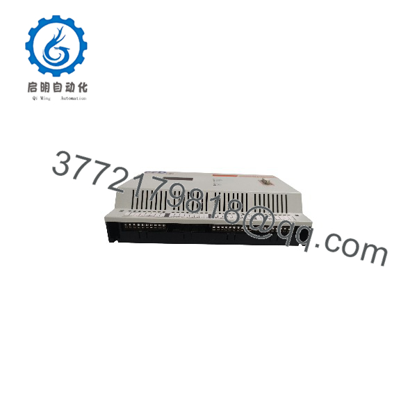
PCD2.M110
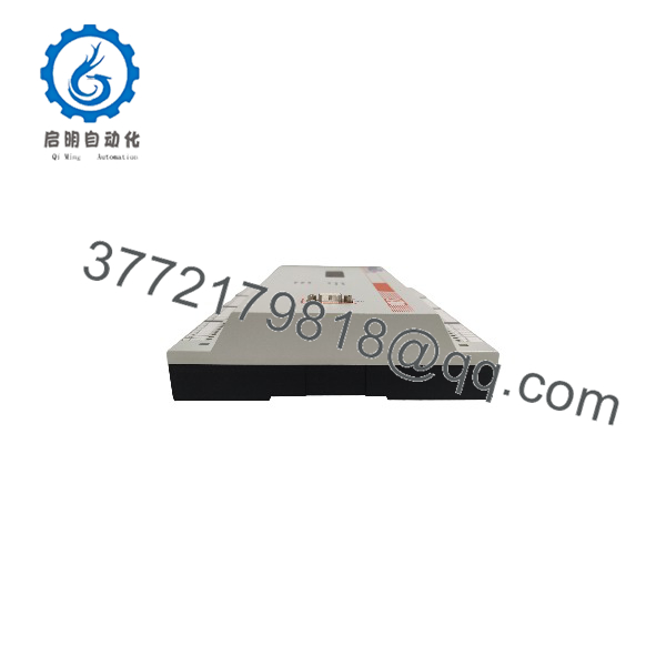
PCD2.M110
Installation & Configuration Guide
Stage 1: Pre-Installation Preparation (≈15 minutes)
⚠️ Safety First: Notify operations of downtime and verify the controlled process is in a safe state — pumps, heaters, and dampers controlled by this PLC need manual or bypass supervision while the CPU is out. Lock out/tag out the 24 VDC supply branch. Wait 5 minutes for internal capacitors to discharge, then verify 0 V at the supply terminals with your multimeter.
- Tools Required: ESD wrist strap, multimeter (Fluke 115 or equivalent), PH1/PH2 screwdrivers, wire labels, a serial cable for PG5 (or the 4-wire S-Bus serial adapter for your PC port configuration), smartphone for photos.
- Data Backup (critical): Connect with PG5 and upload the complete user program, DBs, and text blocks from the old CPU before pulling it. The M110 holds the application in battery-backed RAM — pull a dead-battery module without a backup and the program is gone. Also record: firmware version (read via PG5 or the label on the EPROMs), S-Bus station address, baud rate, and any port configuration. Photograph the module front — DIP switches, address selectors, and the battery position.
Stage 2: Removing the Old Module (≈10 minutes)
- Photograph the CPU module front panel and all socket occupants (which I/O modules sit in which sockets — order matters for addressing).
- Disconnect the 24 VDC supply wiring at the CPU terminal block; label the wires.
- Release the module from the DIN rail/screw mounting and pull it straight out of the housing.
- Check the backup battery condition while it’s on the bench — a leaking battery on a 20-year-old module is common, and it may already have damaged the board. If you see battery leakage, note it: your “spare” old module may be unrevivable, and the new one’s battery is your only program retention.
- Inspect the housing connectors and backplane contacts for corrosion or bent pins.
⚠️ Keep the old module until the replacement runs the full application. If the replacement was supplied without your program, the old module’s battery-backed RAM is your only recovery source.
Stage 3: Installing the New Module (≈15 minutes)
- Ground yourself with the ESD strap — this is a CMOS processor board.
- Verify the nameplate: .M110, and check the hardware version letter matches your expectations (pre-H vs. H affects 5 V bus capacity).
- Verify or install the backup battery in the new module before it ever loses power — a CPU without a battery loses RAM content on power-down.
- Configuration clone (crucial): Set the S-Bus station address and baud rate selectors/DIP switches exactly per your photos. A duplicate or wrong station address on an S-Bus line kills communication with every other station on that bus — I’ve debugged that at 2 AM more than once.
- Firmware check: The M110 stores firmware in two EPROMs. If your replacement ships with different EPROMs than your application requires (PG5 version compatibility matters — older firmware won’t run programs built with PG5 2.0.110 or later and fails with a “Text segment error”), swap the EPROM chips from your old module following ESD handling, or match firmware versions before download. Document the firmware version in your maintenance log.
- Slide the module into the housing until it seats fully, and secure the mounting.
- Reconnect the 24 VDC supply wiring per your labels, and the S-Bus cabling (observe A/B polarity per your photos — S-Bus polarity mix-ups are the number one comms fault after a swap).
Self-Checklist: [ ] Battery installed and fresh, [ ] Station address matches, [ ] Baud rate matches, [ ] S-Bus A/B polarity correct, [ ] Firmware compatible with PG5 project, [ ] Module fully seated.
Stage 4: Power-On & Testing (≈15 minutes)
- Pre-power check: Meter the 24 VDC supply input for correct polarity and level. Meter for shorts between 24 V and 0 V.
- Power the rack. The CPU’s RUN/ERR LEDs are your first indicator — watch for the normal power-up sequence (brief ERR flash during boot, then RUN steady with ERR dark).
- Connect PG5 over the serial link. Verify station address and firmware version read-back before downloading anything.
- Download your backed-up application (program, DBs, texts, and adjust flag/register initial values per commissioning records).
- Put the CPU in RUN and verify: LED state, S-Bus communication with other stations (check each remote station’s diagnostics in PG5), and I/O consistency — force nothing on first pass; observe whether inputs read correctly against known field states.
- Dry-run test: cycle outputs in maintenance mode or via a test routine where the process permits. Verify counters, timers, and any analog scaling behave per the original application.
- Update the maintenance log: new module serial number, hardware version, firmware version, battery replacement date.
⚠️ Troubleshooting Note: Solid ERR LED after download — suspect a firmware/PG5 mismatch (“Text segment error” indicates the program was built with a newer PG5 than the firmware supports; either update firmware via EPROM swap or rebuild the project for compatibility). No S-Bus comms — check station address, baud rate, and A/B polarity in that order. Program lost after power cycle — backup battery missing or dead; the M110’s RAM is not flash. Inputs reading wrong addresses — I/O module socket order differs from the original; addressing on the PCD2 follows socket position.
Total time for an engineer familiar with Saia PCD systems: 40–50 minutes plus program download.
Frequently Asked Questions (FAQ)
Q1: Is the PCD2.M110 obsolete, and is this a genuinely new unit?
Yes — Saia-Burgess Controls (SBC, now part of Honeywell) discontinued the PCD2.M1xx CPU line long ago; it’s in the official SBC product archive. Our stock is New Original / New Surplus: genuine OEM units, never installed, sourced from cancelled projects and distributor liquidations. Every unit is functionally tested — power-up self-test, memory verification, PG5 communication handshake, and an I/O bus check on a genuine PCD2 rack — before it ships. Test photos and videos are available on request. We also offer tested refurbished units at lower cost, clearly labeled as refurbished.
Q2: Will I lose my program when I pull the old CPU?
The program lives in battery-backed RAM on the old module — pull it, and the program stays with the module as long as its battery holds. The risk is a dead backup battery: if it’s flat (common after 20 years), the RAM loses content on power-down. So back the program up via PG5 before removing anything. Honestly, if you’re touching a PCD2.M110 without a PG5 program backup on hand, stop — that’s the single biggest data-loss risk in this whole exercise.
Q3: Can I replace a PCD2.M110 with a newer Saia CPU?
Not directly. The successor PCD2.M5xx0 CPUs use Coldfire “COSinus” technology and run the same I/O modules, but the application must be migrated through PG5 — firmware functions, libraries (e.g., newer DB/text functions), and firmware-specific behaviors differ between the 68k-based M1xx and COSinus platforms. It’s a project, not a swap. If the machine is running fine and you just need hardware replacement, a genuine M110 is the fast path.
Q4: Does the firmware version matter on a replacement?
Yes, more than most buyers expect. The M110 stores firmware in two EPROMs, and PG5 compatibility runs both directions: a program built with PG5 2.0.110 or newer will not run on old firmware — it fails with a “Text segment error” instead of entering RUN. Before ordering, read your existing firmware version (PG5 device status or EPROM labels) and request a unit with matching or compatible firmware. We can also transfer your old EPROMs onto the replacement during testing if you need an exact firmware match — ask before ordering.
Q5: Can I extend the memory or add communication ports?
The 128 KB user memory can be extended with a plug-in RAM chip (Saia tested specific chip types for the PCD2.M110/120/150). Serial communication expands via PCD7.F-series interface modules — e.g., the PCD7.F110 RS-485/422 module on the socket interface. If your application used these, verify they’re present in your replacement or source them together; the CPU alone won’t cover an application that depends on a comms module.
Q6: Why is your price lower than the OEM list price?
Saia no longer manufactures this CPU, so remaining genuine stock comes from cancelled integrator projects and distributor clearances. We acquire at a discount and pass it on — same OEM part, functionally tested and warranted, not a clone. What we won’t do is sell a used unit dressed as new; condition is always stated plainly.
Q7: What warranty do you offer?
New Original units carry a 1-year replacement warranty; refurbished units carry 6 months. Both are tested — power-up sequence, memory read/write verification, PG5 serial handshake, S-Bus port check, and a minimum 24-hour powered run with thermal monitoring — before shipping. Warranty failures get replaced with no restocking fees.