
 WhatsApp: +86 16626708626
 Email:
 Phone: +86 16626708626
Description
Key Technical Specifications
- Full Model: PCD3.M5340
- Description: CPU basic module with Ethernet TCP/IP, 1 MB program memory
- Series: PCD3.M5x40 controllers — “the standard CPU for many applications”
- CPU Speed: 0.3 µs bit operation / 0.9 µs word operation
- User Program Memory: 1 MB (default configuration: 96k program lines, 128k text, 384k ext. memory per family table)
- File System Memory: Expandable to 4 GB with flash memory modules (PCD7.R5xx/R610 flash cards)
- I/O Capacity: Up to 1,023 I/O; 64 I/O module slots; base unit includes 4 slots for I/O, communication, or special modules (e.g., PCD3.Hxxx counter modules)
- Base Unit Interfaces: Ethernet TCP/IP (RJ-45), RS-232/PGU, RS-422/RS-485, USB port for PG5 (USB 1.1 slave device, 12 Mbit/s)
- Ethernet: TCP/IP with integrated web server, FTP server, and file system; Ether-S-Bus support
- Serial Ports: Port 3 (D-Sub, RS-485/RS-422) for S-Bus, up to 115 kbit/s; bus termination activatable in PG5 Hardware Settings
- ⚠️ Not included: Profibus-DP Slave 1.5 Mbit/s (M5540 only); Profi-S-Net 1.5 Mbit/s on Port 10 (explicitly not with M5340)
- Interrupt Inputs: 2
- Real-Time Clock: Yes (RTC)
- Data Protection: Battery-buffered, 1–3 years depending on ambient temperature
- Battery Module: PCD3.R010 (CR 2032 lithium, Renata), slots on the left expansion
- User Backup: PCD7.R500 flash card option for user program backup
- Programming: PG5 Controls Suite (IL, FBD, Ladder, Grafcet per IEC 61131); Device Configurator for port and hardware settings
- Compatibility: Full PCD3 family — module holders (PCD3.Cxxx), LIOs, RIOs, expansion housings
- Compliance: CE
- Reference Documents: Datasheet 26-474 (Ethernet controller with integral RS-422 variant note); Manual 26-789 PCD3 series
Verify against datasheet 26-474 and the PCD3 manual 26-789 for your hardware revision before ordering.
Product Introduction
The Saia-Burgess PCD3.M5340 is the standard CPU of the PCD3.M5x40 family — a processor base unit carrying 1 MB of user program memory, an integrated Ethernet TCP/IP interface with web and FTP servers, and a file system expandable to 4 GB with flash cards. It executes bit operations in 0.3 µs and coordinates up to 1,023 I/O points across 64 module slots, with USB for PG5 programming.
The base unit provides four module slots directly, expandable with PCD3.Cxxx holders, LIOs, and RIOs over the full PCD3 accessory range. The M5340’s position in the lineup is deliberate: full Ethernet capability (Ether-S-Bus, web HMI, FTP file handling) without the Profibus-DP slave port of the M5540 — for applications where the fieldbus side runs on S-Bus and Modbus rather than DP. Plants run it in building automation, infrastructure control, and machine applications that need web-based monitoring but don’t sit on a Profibus network.
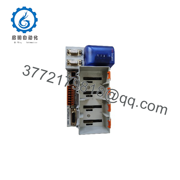
PCD3M.5340
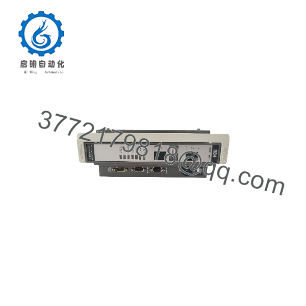
PCD3M.5340
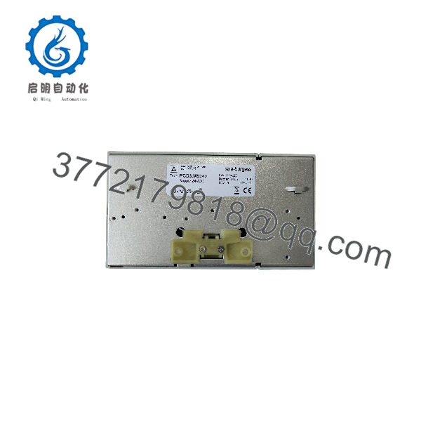
PCD3M.5340
Installation & Configuration Guide
Stage 1: Pre-Installation Preparation (≈15 minutes)
⚠️ Safety First: Notify operations of downtime and place the process in a safe state. Lock out/tag out the 24 VDC supply branch feeding the rack. Wait 5 minutes for capacitor discharge, then verify 0 V at the supply terminals with your multimeter.
- Tools Required: ESD wrist strap, multimeter (Fluke 115 or equivalent), PH1/PH2 screwdrivers, wire labels, USB cable (USB 1.1 slave port for PG5), Ethernet patch cable, smartphone for photos.
- Data Backup: Photograph the module layout — base unit slots, battery module position on the left expansion, flash cards in the memory slots, and the RUN/STOP switch state. Then connect PG5 over USB and upload the complete application: program, DBs, text blocks, plus the Device Configurator settings — port 3 S-Bus parameters, Ethernet IP configuration, and any bus termination activation in Hardware Settings. Record the firmware version read-back. If the application uses the flash file system (HMI pages, data logs), export those files via FTP over Ethernet before pulling the unit — that’s the fast path and it works while the CPU is still running.
Stage 2: Removing the Old CPU (≈15 minutes)
- Put the CPU in STOP via the RUN/STOP switch before removing power.
- Photograph all connections: Ethernet RJ-45, serial D-Subs (label Port 0 vs Port 3 — they look similar and a mix-up costs an hour of confusion later), USB, and the supply terminals.
- Disconnect cabling, then release the CPU from the DIN rail/housing and slide it straight out. This is a base-unit-with-backplate design; do not pry sideways.
- Remove the battery module and any flash cards from the old CPU and set them aside for transfer to the replacement.
- Inspect the housing contacts for corrosion, and check the battery module for leakage on older units.
⚠️ Keep the old CPU until the replacement runs the full application. The flash cards may hold your only copy of HMI pages and logged data.
Stage 3: Installing the New CPU (≈20 minutes)
- Ground yourself with the ESD strap before opening the ESD bag.
- Verify the nameplate: .M5340 — and this is where the family bites people: the M5340 has NO Profibus-DP slave port and NO Profi-S-Net 1.5 Mbit/s. If your application talks Profibus-DP to a master or runs Profi-S-Net at 1.5 Mbit/s, you need the M5540 — installing the M5340 in that role fails comms entirely. This is the most common ordering mistake on this family, so verify against your network topology before the downtime window.
- Memory transfer: Install the flash cards (same slots as photographed) and the battery module into the new CPU. If the application uses PCD7.R500 for user program backup, that card belongs in the new unit too.
- Replace the battery on principle — the PCD3.R010 uses a CR 2032 with 1–3 years buffering; a new-surplus unit may carry an aged cell. A dead battery silently kills RAM retention on the next power cycle.
- Insert the CPU into the housing until it seats and locks; secure the mounting.
- Reconnect cabling per your labels and photos — Ethernet, serial ports, supply.
Self-Checklist: [ ] Correct CPU type verified against network needs, [ ] Flash cards installed in correct slots, [ ] Battery module with fresh cell, [ ] Serial ports correctly assigned (Port 0 vs Port 3), [ ] RUN/STOP in STOP, [ ] Module fully seated.
Stage 4: Power-On & Testing (≈15 minutes)
- Pre-power check: Meter the 24 VDC supply for polarity and level; check for shorts between 24 V and 0 V.
- Power the rack with the CPU in STOP. Watch the status LEDs on the battery module — normal power-up, no error indication.
- Connect PG5 via USB. Verify firmware version read-back before downloading anything.
- Download the complete application (program, DBs, texts, Device Configurator settings). Verify the Ethernet IP took effect — ping the port and confirm Ether-S-Bus/S-Bus stations respond.
- Switch to RUN. Verify: inputs read correctly against known field states, web server responds on the new unit (browse to the CPU’s IP and confirm device pages load — a quick sanity check that the file system and flash cards transferred correctly), and FTP access works if your application uses it.
- Dry-run test where the process permits, then update the maintenance log: serial number, hardware revision, firmware version, battery replacement date.
⚠️ Troubleshooting Note: CPU won’t enter RUN after download — most commonly a firmware/PG5 mismatch; check the device profile against the read-back firmware version. Ethernet dead — verify IP/subnet in Device Configurator and the switch port; don’t assume the module is bad before the config checks out. Serial comms dead on Port 3 — confirm the S-Bus parameters and the bus termination setting in PG5 Hardware Settings; note that on M5340 units produced from early 2012, activating port 3 termination can log a “RESISTERS FAIL” history entry due to a known firmware error — check the SBC support FAQ for your firmware version before chasing hardware. Data lost after power cycle — battery module dead or missing.
Total time for an engineer familiar with PCD3 systems: 50–60 minutes including application download.
Frequently Asked Questions (FAQ)
Q1: What’s the exact difference between the PCD3.M5340 and the M5540?
One port, and it matters. The M5540 adds the Profibus-DP Slave interface at 1.5 Mbit/s (and Profi-S-Net capability on Port 10). The M5340 has Ethernet TCP/IP, S-Bus over RS-485/RS-422 at up to 115 kbit/s, and that’s the comms story. Everything else — 1 MB memory, 1,023 I/O, CPU speed, housing — matches. If your controller is a DP slave under a Siemens or other DP master, order the M5540; ordering the M5340 for that role is a dead controller on the bus. Conversely, if you’re purely Ethernet/S-Bus, the M5340 is the cheaper correct choice.
Q2: Is the PCD3.M5340 still in production, and is this a genuinely new unit?
It’s an active product in the Saia-Burgess Controls (Honeywell) portfolio with current documentation (datasheet 26-474, manual 26-789). We supply New Original / Factory Sealed units in genuine OEM packaging, functionally tested before shipping — power-up self-test, memory read/write verification, PG5 communication over USB, Ethernet port ping and web server check — with test photos/videos available on request. Refurbished units are available at lower cost, labeled exactly as refurbished.
Q3: Will I lose my program when I swap the CPU?
Not if you back up first. The application lives in battery-backed RAM; the flash cards hold the file system and optionally the user program backup (PCD7.R500). Upload everything via PG5 and export the file system via FTP before pulling the old unit, then transfer the flash cards and battery module to the new CPU. One honest caveat: if the old CPU’s battery is dead, the RAM may already be compromised — but the flash backup saves you if it exists. Check whether your site uses PCD7.R500 backup; if it doesn’t, propose it after this swap. It’s cheap insurance.
Q4: Can I expand the memory or add Profibus later?
Memory yes — flash modules expand the file system to 4 GB, and there are dedicated cards for specific uses (PCD7.R500 program backup, PCD7.R551M04 general storage). Profibus-DP slave, no — that’s a hardware difference, not an add-on. If you need DP later, the path is replacing the CPU with an M5540, or adding a communication module per the PCD3 accessory range if your application supports it. Verify with the current accessory documentation before counting on it.
Q5: How do I terminate the RS-485 bus on Port 3?
Through PG5 Hardware Settings — the M5340’s port 3 bus termination is software-activated, not a physical switch. One known wrinkle: units produced from early 2012 can log a “RESISTERS FAIL” entry in the PCD history when termination is enabled, due to a firmware error rather than actual hardware failure. If you see that entry and comms are otherwise healthy, check the SBC support FAQ and your firmware version before ordering replacement hardware. I’ve seen perfectly good CPUs swapped out over that log entry.
Q6: Why is your price lower than the OEM list price?
We’re not an authorized distributor. We buy genuine OEM stock through surplus and wholesale channels — cancelled projects, distributor overstock — and price to move it. Same factory part, same datasheet performance, functionally tested and warranted by us. Condition is always stated plainly: New Original, New Surplus, or Refurbished. No clones, no blurring.
Q7: What warranty do you offer?
New Original: 1-year replacement warranty. Refurbished: 6 months. Every unit is tested before shipping — power-up self-test, memory verification, PG5 handshake over USB, Ethernet port check, and a minimum 24-hour powered run with thermal monitoring — documented in a signed test report. Warranty failures are replaced, no restocking fees, no arguments about installation technique.



