WhatsApp: +86 16626708626
 Email:
 Phone: +86 16626708626
Description
Key Technical Specifications
- Full Model: PCD3.M5540
- Product Description: CPU basic module with Ethernet TCP/IP and Profibus-DP Slave 1.5 Mbit/s
- Series: PCD3.Mxxx0 (modular cassette design)
- Processor: High-performance CPU, Coldfire-based (Saia PCD® COSinus technology); roughly 5× faster than PCD2.M170
- User Program Memory: 1 MB (expandable with flash memory modules; μSD flash card on later hardware)
- Counting Registers: 1,600 with 31-bit counting capacity (2,147,483,647)
- I/O Capacity: Up to 1,023 I/O; 64 I/O module slots; I/O expansion via PCD3.Cxxx module holders
- Integrated Interfaces: Ethernet TCP/IP (RJ-45), RS-485 (Port 2, S-Net/MPI/Profibus), RS-232/PGU (Port 0), USB port for PG5 programming unit
- Communication Protocols: S-Bus, Ether-S-Bus, Ethernet TCP/IP, Profibus-DP (slave), Profi-S-Net, Modbus; BACnet with optional flash memory module
- Web Server: Integrated web, FTP server, and file system
- Interrupt Inputs: 2
- Battery Backup: Battery module (PCD3.R010, CR 2032 lithium), data protection 1–3 years depending on ambient temperature
- Status Indicators: LEDs on battery module indicate CPU and battery status and signal errors
- Controls: RUN/STOP switch; two memory module slots; two additional communication interface slots
- Internal 5 V Bus Loading Capacity: max. 600 mA
- Supply: 24 VDC system supply (per PCD3 system requirements)
- Programming: PG5 (IL, FBD, Ladder, Grafcet, structured text per IEC 61131)
- Compatibility: Full PCD3 family — expansion cassettes, local/remote I/O, communication and function modules, accessories
- Compliance: CE, EAC (machinery exports to Russia, Kazakhstan, Belarus)
Verify against datasheet PP31-662 for your hardware revision before ordering.
Product Introduction
The Saia-Burgess PCD3.M5540 is the high-end CPU basic module of the PCD3.M5xx0 family — a modular cassette-design processor carrying 1 MB of user program memory, an integrated Ethernet TCP/IP interface with web and FTP servers, and a Profibus-DP Slave port at 1.5 Mbit/s. It coordinates up to 1,023 I/O points across 64 module slots, expandable through the full PCD3 accessory range.
Its strength is communications density: up to 13 communication interfaces when fully expanded with the cassette system, running S-Bus, Ether-S-Bus, Profibus-DP, Modbus, and optional BACnet simultaneously. That’s why plants pick it over mid-range CPUs for building automation, water/wastewater, energy management, and machine control where one controller handles multiple protocols at once. Two interrupt inputs and 1,600 high-speed counting registers cover demanding timing tasks without external hardware.
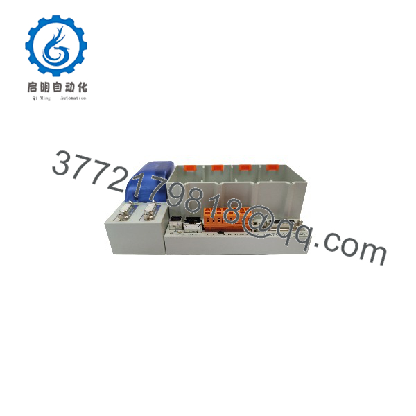
PCD3.M5540
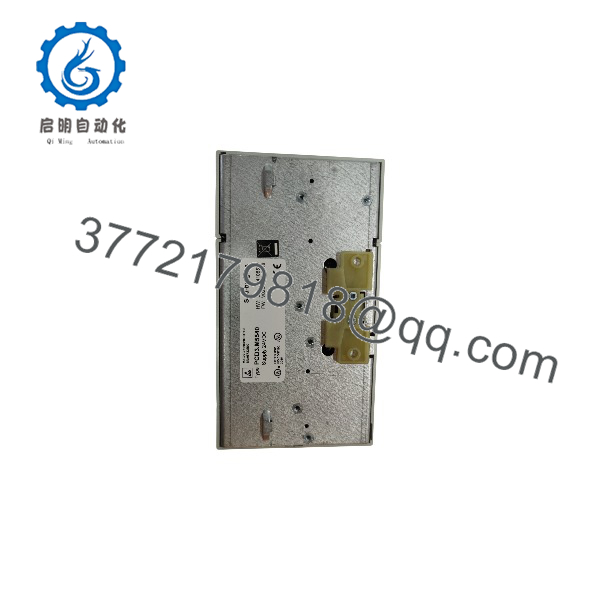
PCD3.M5540
Installation & Configuration Guide
Stage 1: Pre-Installation Preparation (≈15 minutes)
⚠️ Safety First: Notify operations of downtime and place the controlled process in a safe state — this CPU likely runs a large I/O footprint, so coordinate manual/bypass supervision for anything safety-relevant. Lock out/tag out the 24 VDC supply branch. Wait 5 minutes for capacitor discharge, then verify 0 V with a multimeter at the supply terminals.
- Tools Required: ESD wrist strap, multimeter (Fluke 115 or equivalent), PH1/PH2 screwdrivers, wire labels, USB cable for PG5 (or Ethernet patch cable), smartphone for photos.
- Data Backup: Photograph the full module layout — every cassette slot occupant, battery module position, flash card presence, and the RUN/STOP switch state. Then connect PG5 (USB is the standard PGU port) and upload the complete application: program, DBs, text blocks, and firmware version read-back. Record the Ethernet IP settings (or the S-Bus station address on serial ports) — write down every port number’s configuration. Also export the file system contents from the flash card if your application stores HMI pages or data logs there.
Stage 2: Removing the Old CPU (≈15 minutes)
- Put the CPU in STOP via the RUN/STOP switch before killing power — cleaner than a hard power cut for a controller with this many comms sessions.
- Photograph the cassette layout and note which memory/communication modules occupy the two module slots and the battery slot.
- Disconnect Ethernet (RJ-45), RS-485/RS-232 serial connections, and the USB if attached. Label the serial lines — Port 0 (RS-232/PGU) and Port 2 (RS-485) look similar and mixing them up costs you an hour of head-scratching later.
- Release the module from the DIN rail/housing and slide it straight out of the base — this is a cassette design; do not pry it sideways or you’ll bend the backplane contacts.
- Remove the battery module and flash memory card from the old CPU and set them aside — you may want to transfer them to the replacement (see Stage 3).
⚠️ Keep the old CPU until the replacement runs the full application. The flash card on the old unit may be your only copy of the file system and HMI pages.
Stage 3: Installing the New CPU (≈20 minutes)
- Ground yourself with the ESD strap before opening the ESD bag.
- Verify the nameplate: .M5540 — and confirm hardware revision compatibility if your application relies on specific firmware features (later hardware integrates a μSD flash card slot).
- Memory transfer (crucial): If the replacement ships without a flash memory module, transfer the flash card and battery module from the old CPU. The PCD3.M5xx0 has two memory module slots — install them in the same positions as photographed. Note: a BACnet flash module carries the BACnet firmware extension; if your application uses BACnet, the module must go into the new CPU or the stack is absent.
- Verify battery condition: The PCD3.R010 battery module uses a CR 2032 lithium cell with 1–3 years buffering depending on temperature. On a new-surplus unit, replace the battery on principle — a dead battery silently loses RAM retention on the next power cycle.
- Configuration check: Ethernet IP, S-Bus addresses, and port configurations live in the application, which you’ll download — but confirm the PG5 device profile matches the firmware version you read from the old CPU before downloading.
- Insert the CPU into the base until it seats fully and locks; secure the DIN/housing mounting.
- Reconnect serial and Ethernet cabling per your labels and photos.
Self-Checklist: [ ] Flash card(s) installed, [ ] Battery module installed with fresh cell, [ ] Module slots match photo, [ ] RUN/STOP in STOP, [ ] Ethernet/serial cables on correct ports.
Stage 4: Power-On & Testing (≈15 minutes)
- Pre-power check: Meter the 24 VDC supply input for polarity and level; check for shorts between 24 V and 0 V.
- Power the rack. With the CPU in STOP, the battery-module LEDs indicate power and CPU status — all should be normal, no error indication.
- Connect PG5 via USB. Verify firmware version read-back and station identity before downloading anything.
- Download the complete application (program, DBs, texts, initial values). Verify IP settings and port configurations took effect — ping the Ethernet port and confirm S-Bus stations respond.
- Switch the CPU to RUN via the switch or PG5. Watch the status LEDs — solid error indication after download points to a firmware/application mismatch.
- Dry-run test: verify inputs read correctly against known field states, cycle outputs in maintenance mode where the process permits, and confirm Profibus-DP and Ethernet devices reconnect (drives, HMIs, remote I/O).
- Update the maintenance log: serial number, hardware revision, firmware version, battery replacement date.
⚠️ Troubleshooting Note: CPU won’t enter RUN after download — most commonly a firmware/PG5 mismatch; if it still refuses after 2 minutes per the hardware manual, the unit needs repair evaluation, don’t force it. No Ethernet comms — check IP/subnet config and the switch port, and confirm the device profile in PG5 matches. Profibus-DP slave not connecting — verify bus parameters and termination on the DP line. Lost data after a power cycle — battery module missing or dead; RAM retention is battery-backed, not flash, unless your application explicitly uses the flash file system.
Total time for an engineer familiar with PCD3 systems: 50–60 minutes including application download.
Frequently Asked Questions (FAQ)
Q1: Is the PCD3.M5540 obsolete, or current production?
The PCD3.M5xx0 family remains part of the active Saia-Burgess Controls (Honeywell) portfolio — it’s a mature, fully supported platform, with PG5 support and firmware maintenance continuing. We sell New Original / Factory Sealed units in genuine OEM packaging, sourced through official and surplus channels. Every unit is functionally tested before shipping, with test photos/videos available on request. If you want documented channel provenance for a warranty-critical installation, ask and we’ll state the exact sourcing plainly.
Q2: What’s the difference between the PCD3.M5540 and the PCD3.M5340?
The M5540 includes the Ethernet TCP/IP interface; the M5340 does not. Everything else — 1 MB memory, Profibus-DP slave, I/O capacity — matches the datasheet. If your application uses the web server, Ether-S-Bus, or any TCP/IP device (HMIs, SCADA), you need the M5540. Ordering the wrong one is the most common procurement mistake on this family.
Q3: Will I lose my program when I swap the CPU?
Not if you follow procedure. The application lives in battery-backed RAM; the flash memory module holds the file system, HMI pages, and optionally the application backup. Two safety nets: upload the full application via PG5 before pulling the old CPU, and transfer the flash card to the new unit. Also note the battery module buffers RAM for 1–3 years — if the old CPU’s battery is dead, the program may already be at risk, so treat the PG5 upload as mandatory, not optional. Honestly, the PG5 backup takes ten minutes and has saved me more than once.
Q4: Can I upgrade from an older PCD3 or PCD2 CPU to the M5540?
Within PCD3, yes — the M5xx0 CPUs use the same cassettes, I/O modules, and accessories, and PG5 migrates the project cleanly. From PCD2, the hardware changes completely (different housing, different I/O modules), though PG5 supports project migration from PCD2 68k-era controllers with recompilation and function review. Budget real engineering time for a PCD2→PCD3 migration, not a swap window.
Q5: Does this CPU support BACnet?
With the optional BACnet flash memory module installed, yes — the module carries the BACnet firmware extension, and PCD3.M5540 is on the supported controller list. Without it, no BACnet stack. If your building-automation application needs BACnet, confirm the flash module is included in your order or transfer it from the old CPU.
Q6: Why is your price lower than the OEM factory list price?
We’re not an authorized distributor — we buy genuine OEM stock through surplus and wholesale channels (cancelled projects, distributor overstock) and price to move it. Same part, same factory build, functionally tested and warranted by us rather than the manufacturer. We state condition plainly on every listing: New Original, New Surplus, or Refurbished — no blurring.
Q7: What warranty do you offer?
New Original units: 1-year replacement warranty. Refurbished units: 6 months. Every unit is tested before shipping — power-up self-test, memory read/write verification, PG5 communication over USB, Ethernet port check with ping/Ether-S-Bus handshake, and a minimum 24-hour powered run with thermal monitoring. Warranty failures are replaced, no restocking fees.