WhatsApp: +86 16626708626
 Email:
 Phone: +86 16626708626
Description
Key Technical Specifications
- Full Model: PCD3.W315
- Description: Analog input module, 7 inputs, 0…20 mA (4…20 mA configurable via Device Configurator)
- Series: PCD3.W3x5 (electrically isolated input modules)
- Input Channels: 7 (E0…E6)
- Signal Range: 0…20 mA (input impedance 120 Ω)
- Configurable Range: 4…20 mA settable in firmware parameters
- Resolution: 12 bits (0…4,095)
- Accuracy: ± 0.15% at 25 °C (corresponds to 30 µA)
- Temperature Coefficient: ± 0.01% / K
- Input Time Constant: 2.4 ms
- Cut-Off Frequency: 65 Hz
- Potential Isolation: Yes, 500 VDC — galvanic separation of inputs to CPU; channels themselves are not separated from each other
- Overcurrent Protection: ± 35 mA
- Current Draw (internal 5 V bus): Max. 60 mA
- Terminal: 14-pole terminal block (E0…E6 and GND)
- Connection: Signals wired to E0…E6; single common GND reference
- Evaluation: Firmware reads values per Device Configurator settings; FBox “PCD2/3.W3x5” available in PG5 for scaling
- Dimensions: 56 × 97 mm
- Compatibility: PCD3 controllers, PCD3 RIO head stations, and PCD3.Cxxx module holders; also usable on older PCD controllers with Step®7-compatible operating systems (Saia PCD xx7 series)
- Compliance: CE
- Reference Documents: Data sheet 31-634; Manual 27-600 (I/O modules for PCD1/PCD2/PCD3)
Note the isolation architecture before ordering: the module isolates all inputs as a group from the CPU, but channels share a common ground among themselves. Applications needing channel-to-channel isolation require a different module or external isolators.
Product Introduction
The Saia-Burgess PCD3.W315 is a 7-channel analog input module for the PCD3 controller family, measuring 0…20 mA signals at 12-bit resolution with ± 0.15% accuracy. It connects via a 14-pole terminal block with channels E0 through E6 sharing a common ground reference, galvanically isolated as a group from the CPU at 500 VDC.
Typical signals: 4…20 mA transmitters — pressure, flow, level, temperature — wired as current loops terminated at 120 Ω input impedance. The 4…20 mA mode is a firmware parameter set through the Device Configurator in PG5, with the “PCD2/3.W3x5” FBox handling scaling into engineering units. Plants run these modules across building automation, water treatment, and process monitoring where one module covers seven transmitter loops compactly and the isolation from the CPU keeps ground-loop noise out of the digital side.
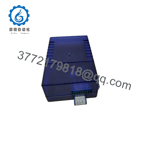
PCD3.W315
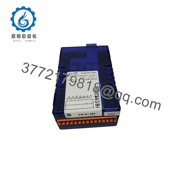
PCD3.W315
Installation & Configuration Guide
Stage 1: Pre-Installation Preparation (≈10 minutes)
⚠️ Safety First: Notify operations of downtime and identify which transmitters feed the module — losing seven analog channels means seven control loops potentially reading zero, so coordinate with operations on what the PLC will do on input loss. Lock out/tag out the 24 VDC supply branch feeding the rack. Wait 5 minutes, then verify 0 V at the supply terminals with a multimeter.
- Tools Required: ESD wrist strap, multimeter (Fluke 115 or equivalent, mA range), PH1 screwdriver, wire labels, smartphone for photos.
- Data Backup: The official rule for this family is strict: I/O modules and I/O terminal blocks may only be plugged in or removed when the CPU and the external +24 V are disconnected from the power supply. Not de-energizing the backplane before removing I/O risks backplane contact damage. Photograph the terminal block wiring — all 14 poles — and record the Device Configurator settings for this module (range mode 0…20 vs 4…20 mA, any gain corrections, FBox scaling in the PG5 project).
Stage 2: Removing the Old Module (≈10 minutes)
- Confirm power is off at the rack — this is not a hot-pluggable module per the manufacturer’s own documentation.
- Photograph the 14-pole terminal block completely: which loop is on which channel, and the GND commons.
- Release the terminal block(s) from the module — Saia modules typically have a release tab at the top of the terminal block. Do not pry with a screwdriver against the housing.
- Release the module from its slot in the module holder per the PCD3 manual and pull straight out.
- Inspect the module holder slot contacts for corrosion, and check the terminal block for heat marks — a discolored terminal on a current-input module means a loop fault (see Troubleshooting below).
⚠️ Keep the old module on the bench until the replacement reads correctly. Comparing channel behavior between old and new is your fastest diagnostic tool.
Stage 3: Installing the New Module (≈10 minutes)
- Ground yourself with the ESD strap before opening the ESD bag — this is a precision analog board.
- Verify the nameplate: .W315 — and note there are three siblings in the W3x5 family: W305 is voltage (0…10 V), W315 is current (0…20 mA), W325 is ±10 V. They are physically similar; ordering or installing the wrong sibling is the most common mistake on this family. The current module has 120 Ω inputs; the voltage modules have ~13.5 kΩ. If your transmitters are 4…20 mA, this is the one.
- No DIP switches on this module — all configuration (0…20 vs 4…20 mA, gain correction) is done in firmware via Device Configurator/PG5, so there is nothing to clone physically. But verify the PG5 project’s Device Configurator entry matches the module slot and type.
- Insert the module into the holder slot until it locks — only with rack power off, per manufacturer documentation.
- Reattach the terminal block(s) with your labeled wiring. Current loops are polarity-sensitive: signal current flows into E0…E6, return via GND. A reversed loop reads zero.
Self-Checklist: [ ] Correct module type (W315, not W305/W325), [ ] Terminal block wiring matches photo, [ ] Loop polarity correct, [ ] Module fully seated with rack power off, [ ] PG5 Device Configurator entry matches slot.
Stage 4: Power-On & Testing (≈15 minutes)
- Pre-power check: With the transmitter loops live (their own supply) but rack off, meter each channel at the terminal block — you should see 4–20 mA flowing through each loop (or whatever the process level dictates). This confirms field-side health before you blame the new module.
- Power the rack. The module has no front LEDs for channel status — verification is done through PG5.
- Connect PG5 and read back the analog values with the debugger/monitor view. Compare against your multimeter mA readings taken at the terminal block: a channel reading 12 mA on the meter should read 2,458 counts (12 mA / 20 mA × 4,095) in 0…20 mode, or the scaled engineering value in your FBox.
- Verify the configuration mode (0…20 vs 4…20) is as designed for each channel — a 4…20 transmitter on a channel configured 0…20 reads fine, but a broken-wire condition is harder to distinguish.
- Dry-run test: with operations watching the process, verify each loop’s engineering-unit value in the PG5 monitor matches field reality — compare a pressure reading against the local gauge, a level against the sight glass.
- Update the maintenance log: serial number, slot position, configuration mode per channel.
⚠️ Troubleshooting Note: One channel reading zero while the meter shows current — check the loop’s return path at the terminal (common GND) and confirm the channel isn’t configured for the wrong range mode. All seven channels dead — suspect the module’s GND connection or a failed backplane contact; reseat with power off. One channel reading wrong-value-but-not-zero — measure the actual loop current with a mA meter in series and compare; if the meter and the module disagree beyond ± 0.15% + scaling error, the module channel is faulty. Channel values drifting with temperature near a heat source — the ± 0.01%/K coefficient adds up in hot cabinets.
Total time for an engineer familiar with PCD3 hardware: 30–45 minutes, including loop verification.
Frequently Asked Questions (FAQ)
Q1: Can I hot-swap this module under power?
No — and this isn’t my opinion, it’s Saia-Burgess’s own documentation: I/O modules and terminal blocks may only be plugged in or removed when the CPU and the external +24 V are disconnected from the power supply. Pulling it live risks backplane contact damage and scrambled readings across the rack. Kill the rack supply, wait, then swap. It costs you five minutes of downtime instead of a damaged module holder.
Q2: Is this module still in production, and is it genuinely new?
Yes — the PCD3.W315 is an active product in the Saia-Burgess Controls (Honeywell) portfolio, with a current datasheet (31-634) and full manual support. We supply New Original / Factory Sealed units in genuine OEM packaging. Each unit is functionally tested before shipping — channel-by-channel injection with a calibrated current source, count read-back, and a powered burn-in — with test photos/videos available on request. Refurbished units are also available at lower cost, labeled exactly as refurbished.
Q3: What’s the difference between the PCD3.W315, W305, and W325?
Signal type. W315 = 0(4)…20 mA current inputs. W305 = 0…10 V voltage inputs. W325 = −10…+10 V. All three are 7-channel, 12-bit, same isolation architecture. They look nearly identical physically. If your transmitters are 4-wire or 2-wire current-loop devices, you need the W315; if your sensors are 0–10 V voltage output (common in building automation with 10 V dampers/valves), you need the W305. I’ve seen whole commissioning days lost to a W305 ordered where a W315 was needed — check the transmitter datasheet before ordering.
Q4: Are the channels isolated from each other?
No. The module provides galvanic separation as a group from the CPU (500 VDC), but the seven channels share a common ground reference. For most 4…20 mA loops this is fine — all transmitters referenced to one common. But if your loops come from different panels with different ground potentials, you’ll see cross-channel interference or ground-loop currents. In that case, use external signal isolators per loop, or restructure the loops so they share one clean common.
Q5: How do I configure 4…20 mA mode instead of 0…20 mA?
Through the PG5 Device Configurator — it’s a firmware parameter, not a DIP switch. Set the range mode for the module in the device configuration, download to the CPU, and handle scaling with the “PCD2/3.W3x5” FBox in your application. Take a photo of your existing configuration screen before swapping anything, and back up the PG5 project — module configuration lives in the CPU project, so a replacement module picks it up automatically on download.
Q6: Why is your price lower than the OEM list price?
We’re not an authorized distributor — we source genuine OEM stock through surplus channels and distributor overstock (cancelled projects, liquidated inventory) and pass the discount on. Same factory part, same datasheet performance, warranted by us instead of the manufacturer. We state condition plainly: New Original, New Surplus, or Refurbished. No blurring, no clones.
Q7: Calibrated current source testing: what does your QC actually cover?
For this module specifically: inbound inspection against OEM packing and serial traceability, visual inspection, then live functional test on a genuine PCD3 rack — calibrated current injection on each of the 7 channels at 0%, 25%, 50%, 75%, 100% of span, count read-back verification in PG5, insulation resistance check (>10 MΩ at 500 V Megger, consistent with the module’s own isolation rating), a minimum 24-hour powered run, and a signed test report. Test videos and photos available on request. We say “verified fully functional under load testing” — not “100% failure-proof,” because no honest engineer says that.