
 WhatsApp: +86 16626708626
 Email:
  Phone: +86 16626708626
Description
3. Key Technical Specifications
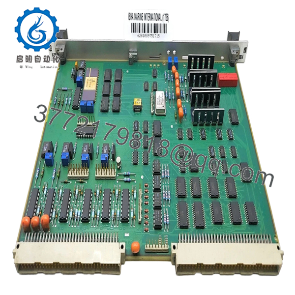
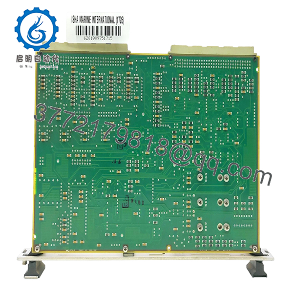
- Product Type: PCB control card
- Application: Marine automation / navigation control systems
- Controller Platform: Proprietary automation platform (“Automate”)
- Part Number: GE3016G325
- System Role: Signal processing and control interface board
- Mounting: Rack or enclosure-installed PCB
- Supply Voltage: Typically 24 V DC (marine control standard, verify per system)
- Communication: Internal backplane / proprietary bus
- Operating Environment: Marine-rated (vibration, humidity exposure typical)
- Market Condition: Primarily used or refurbished units
⚠️ Note: No public datasheet with full electrical specs is available. This is OEM-integrated hardware—verify pinout and function against the vessel/system manual before installation.
4. Product Introduction
The SAM Electronic GE3016G325 is a marine control PCB card used in navigation or automation systems, commonly associated with STN Atlas and legacy ship control platforms. It functions as a signal processing and interface board within a proprietary control architecture.
In real-world deployments, this board is not interchangeable with standard PLC hardware. It is tightly bound to system firmware and backplane architecture. Most units available today are reclaimed from vessels or refurbished stock, so hardware condition and connector integrity are key concerns during replacement.

- GE3016G325
- GE3016G325
5. Installation & Configuration Guide
Stage 1: Pre-Installation Preparation (Estimated Time: 15 minutes)
- ⚠️ Safety First:
Isolate control system, apply lockout/tagout, verify zero voltage, wait 5 minutes. - Tools Required:
ESD strap, PH1 screwdriver, Fluke 115 multimeter, labeling tags, smartphone. - Data Backup:
- Record system role of the board (slot position matters)
- Photograph connectors and wiring harnesses
- Document any system alarms or fault codes
Stage 2: Removing the Old Module (Estimated Time: 10 minutes)
- Open cabinet or rack enclosure.
- Label all connectors—marine systems often reuse identical plugs.
- Disconnect wiring carefully (no force on aged connectors).
- Release locking mechanism.
- Pull PCB straight out to avoid backplane damage.
- ⚠️ Note: Keep the old board for comparison during commissioning.
Stage 3: Installing the New Module (Estimated Time: 10–15 minutes)
- Wear ESD protection.
- Verify exact model: GE3016G325 (no variant mismatch).
- Insert module into rack—ensure full seating.
- Reconnect wiring exactly as documented.
- Secure any retention hardware.
Self-Checklist:
- Correct slot position
- Connectors matched exactly
- No bent pins
- Grounding intact
Stage 4: Power-On & Testing (Estimated Time: 20 minutes)
- Pre-Power Check:
Confirm stable 24 V DC supply and no shorts.
Power-On Steps:
- Power system without activating field devices.
- Observe system diagnostics or HMI alarms.
- Verify board recognition in system.
- Perform functional checks (signal simulation if possible).
- Confirm stable operation.
- ⚠️ Troubleshooting Note:
- No detection → Check slot position and backplane alignment
- Fault alarms → Likely firmware or configuration mismatch
- Intermittent faults → Check connector oxidation (very common in marine systems)
6. Frequently Asked Questions (FAQ)
Q1: Is this a standard PLC module?
No. This is OEM marine hardware. It will not function in Siemens, ABB, or Rockwell systems.
Q2: Is GE3016G325 still manufactured?
No. Market availability is almost entirely used or refurbished units.
Q3: Can I use a different GE3016 variant?
Not safely. Even similar model numbers can have different firmware or pin assignments. Match exactly or expect faults.
Q4: What’s the most common failure mode?
Connector and contact degradation. In marine environments, oxidation is a constant issue—more than actual component failure.
Q5: Can this board be hot-swapped?
No. These systems are not designed for live insertion. You risk damaging the backplane or corrupting system state.
Q6: Why is pricing so inconsistent?
Supply comes from dismantled vessels and surplus inventory. Condition varies widely—from clean pulls to heavily exposed boards.
Q7: What’s the biggest installation mistake?
❗ Incorrect slot placement or connector mismatch.
I’ve seen identical boards installed in the wrong slot—system booted with multiple faults and no clear diagnostics.


