
 WhatsApp: +86 16626708626
 Email:
  Phone: +86 16626708626
Description
Key Technical Specifications
| Parameter | Value |
| Circuit Type | Signal Distribution / Interface Board |
| Input Voltage | 24 V DC Nominal |
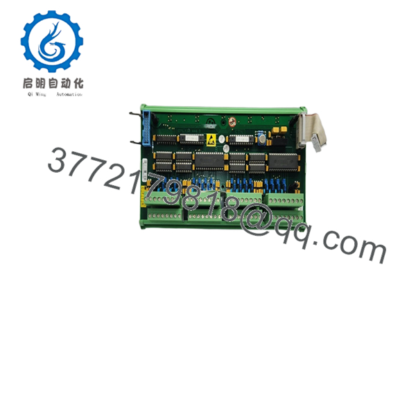
| Connector Type A | High-density Multi-pin Header (System Side) |
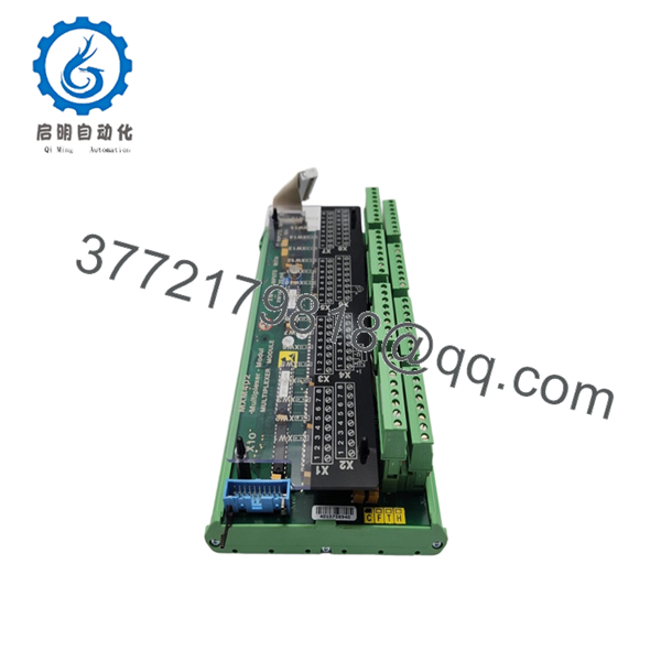
| Connector Type B | Screw-terminal / Phoenix-style blocks (Field Side) |
| Mounting | DIN-rail or specialized chassis mount |
| Housing | Open-frame PCB or Protective Carrier |
| Application | MTU Series 2000/4000 Engine Control Systems |
| Compatibility | MCS-5, Blue Vision, and ADEC architectures |
| Environmental | Conformal coated for humidity and vibration resistance |
Product Introduction & Supply Chain Strategy
The SAM Electronics 271.130 442.F is a specialized interface module utilized within MTU’s ADEC and Blue Vision control ecosystems. It serves as the primary termination point for complex engine harness wiring, converting high-density system connectors into manageable field-side wiring points. This module ensures that signals for engine speed, temperature, and pressure are cleanly routed from the sensors to the central processing units without interference.
Securing this module as New Surplus is a vital supply chain tactic for aging industrial and marine assets. Interface boards like the 271.130 442.F are “silent failure” points; over years of service, thermal expansion and vibration can lead to hairline cracks in solder joints or localized oxidation on terminal pins. By choosing New Surplus, you bypass the risks of refurbished boards that may have undergone “cold-solder” repairs. Investing in original new stock guarantees zero-hour electrical integrity, maintaining the Total Cost of Ownership (TCO) by preventing intermittent signal loss that leads to unplanned engine derates or shutdowns.

- 271.130 442.F
- 271.130 442.F
Installation & Configuration Guide
Stage 1: Pre-Installation (Prep & Safety)
Perform a full lock-out/tag-out of the engine control system. Ensure the 24 V DC supply is isolated. Use a grounded ESD wrist strap, as the board contains sensitive trace paths. Use a high-resolution camera to document every wire position on the existing terminal blocks before removal.
Stage 2: Removal
Unplug the high-density system connectors first by releasing any retaining clips. If the unit uses screw terminals, loosen them and carefully pull the wires. If it uses pluggable terminal blocks, pull the entire block away from the PCB. Unclip the module from its DIN-rail or chassis mounting plate.
Stage 3: Installation (Clone & Seat)
Mount the new 271.130 442.F onto the rail. Reconnect the system-side multi-pin headers first to ensure proper alignment. Transfer the field wiring or plug the terminal blocks into the new board. Ensure all connections are tight; a loose signal wire on this board can cause a catastrophic “False Sensor Fault” during operation.
Stage 4: Power-On & Testing
Energize the control system. Monitor the HMI for any “I/O Communication” errors. Use a multimeter to verify 24 V DC is present at the designated power pins. Perform a manual sensor check (e.g., toggling a level switch) to confirm the signal is correctly passing through the interface board to the ECU.
Firmware/Software Versions & Upgrade Notes
As a terminal/interface module, the 271.130 442.F is largely hardware-based and does not typically house programmable firmware. However, the “442.F” revision suffix is critical. Hardware revisions in these modules often include updated resistor values or bridge traces to accommodate newer sensor types. Always ensure you are replacing like-for-like; installing an older “D” or “E” revision in place of an “F” revision can lead to signal impedance mismatches that the ADEC controller will flag as a hardware error.
Frequently Asked Questions (FAQ)
- Is this a passive board or does it have active components?
The 271.130 442.F is a hybrid; it primarily distributes signals but includes protection diodes and filtering capacitors to stabilize the 24 V DC power rail.
- Why should I avoid buying a used version of this board?
Interface boards in engine rooms are subject to constant “micro-vibrations.” In used boards, the copper traces near the terminals often develop fatigue cracks that are invisible to the naked eye but cause intermittent failures under load.
- Does this come with the pluggable terminal blocks?
Surplus units often ship as the PCB/Chassis only. We recommend reusing your existing terminal blocks if they are in good condition, or sourcing new ones if the old pins show signs of arcing or corrosion.
- Is the “442.F” version compatible with Blue Vision Basic?
Yes, this revision is commonly found in Blue Vision and MCS-5 configurations. Always verify the part number on your existing unit’s label.
- What is the lead time for this specific SAM Electronics part?
As this is New Surplus stock, we typically offer same-day or next-day shipping, bypassing the lengthy manufacturing lead times for legacy SAM components.
- What warranty is provided?
This unit carries a 1-year functional warranty. If the module fails to pass signals or exhibits electrical defects during commissioning, it is covered for replacement or refund.


