
 WhatsApp: +86 16626708626
 Email:
  Phone: +86 16626708626
Description
3. Key Technical Specifications
| Parameter | Value |
|---|---|
| Model Number | EMP-2200M (815.001.200.01) |
| Power Supply | 220 VAC ±15%, 50/60 Hz |
| Power Consumption | 45 VA typical |
| Processor Type | 32-bit RISC (custom Sam Electronics ASIC) |
| Clock Speed | 200 MHz |
| User Memory | 8 MB SRAM (battery-backed) |
| Program Memory | 16 MB Flash |
| Retentive Memory | 512 KB |
| I/O Capacity | Up to 2048 local I/O points |
| Communication Ports | 2 x Ethernet (10/100Base-T), 2 x RS-485, 1 x RS-232 |
| Supported Protocols | Modbus RTU/TCP, Profibus DP (with external module), Sam Marine Bus |
| Redundancy | Hot-standby pair capable (requires second unit and sync cable) |
| Operating Temperature | 0°C to +55°C |
| Storage Temperature | -25°C to +70°C |
| Humidity | 95% non-condensing |
| Protection Rating | IP20 |
| Dimensions (W x H x D) | 270 x 210 x 85 mm |
| Weight | 2.8 kg |
| Battery Type | Lithium (BR2032 or CR2450 depending on revision) |
| Battery Life | 5 years typical |
4. Product Introduction
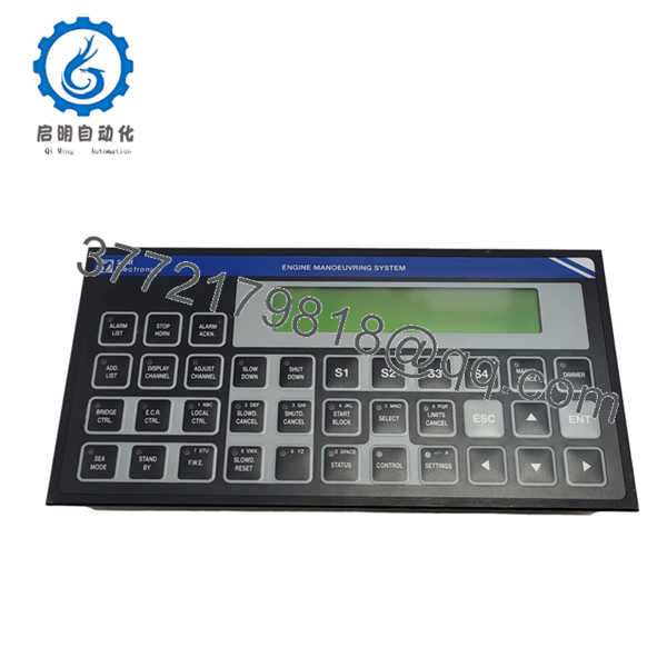
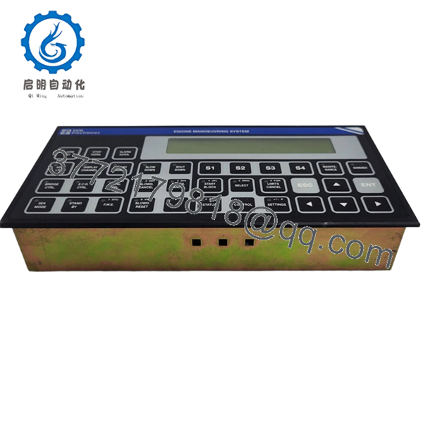
The Sam Electronics EMP-2200M (815.001.200.01) is a main processor module designed for the Sam Electronics 6000 Series Marine Automation Platform. It serves as the central CPU for engine room control, power management systems (PMS), and auxiliary machinery monitoring on vessels ranging from offshore supply vessels to cargo ships.
This unit runs the Sam Marine OS real-time kernel and supports standard IEC 61131-3 programming languages (Ladder, FBD, ST, and SFC). The EMP-2200M distinguishes itself from base models by supporting hot-standby redundancy — a critical feature for DP2/DP3 vessels where single-point CPU failure cannot take down the system. Field experience shows these units running continuously for 10+ years in engine control rooms with proper ventilation.

- EMP-2200M 815.001.200.01
5. Installation & Configuration Guide
Total estimated time for trained technician: 60 minutes (including program transfer)
Stage 1: Pre-Installation Preparation (10 minutes)
⚠️ Safety First: Notify bridge/ECR. Place the affected system in manual mode. Isolate the 220VAC supply to the rack. Lock-out/tag-out (LOTO). Wait 5 minutes for internal power supply capacitors to discharge.
Tools Required:
- ESD wrist strap and mat
- Phillips #2 screwdriver
- 2.5mm flathead screwdriver (terminal blocks)
- Multimeter (Fluke 115 or equivalent)
- PC with Sam Engineering Tool (SET) software version 3.2 or higher
- Programming cable (RS-232 null modem or Ethernet crossover)
- Smartphone for photos
Data Backup (Crucial):
- Connect to the existing EMP-2200M via the RS-232 service port.
- Upload the entire project archive (program, hardware config, and symbol table).
- Export the retentive variables list (critical setpoints, timers, counters).
- Document the Modbus slave ID and TCP/IP settings.
- Photograph all wiring connections and LED statuses.
⚠️ Critical Warning: Do not skip the upload step. The 815.001.200.01 revision has known issues with flash retention after 8+ years. Power-cycling a failed unit without a backup can result in program loss.
Stage 2: Removing the Old Module (10 minutes)
- Remove the front cover (four screws on the corners).
- Locate the battery. If the unit is failed, measure battery voltage (should be >2.8V). Record this for failure analysis.
- Label and disconnect all wiring:
- Power connector (L, N, Ground)
- Ethernet cables (Port A: Redundant bus, Port B: Monitoring/SCADA)
- RS-485 cables (Modbus field devices)
- Redundancy sync cable (if installed)
- Release the backplane locking levers (top and bottom).
- Pull the module straight out from the rack. Do not rock it side to side — you can bend backplane pins.
⚠️ Note: Keep the old module until the new one is fully operational. Some revisions have removable EPROMs that contain the bootloader.
Stage 3: Installing the New Module (15 minutes)
- ESD prep: Grounded wrist strap. Work on ESD mat.
- Inspect the new EMP-2200M:
- Verify model: 815.001.200.01 exactly. The 815.001.200.02 (EMP-2200M/II) has different pinouts.
- Check for bent pins on the backplane connector.
- Verify battery is installed and seated correctly (check the date code on the battery).
- Firmware Verification (Critical):
- The new module’s firmware version must be within ±1 major revision of the old module.
- To check: Power the new unit on a bench (use a separate 220V supply). Connect via RS-232 and read the boot message.
- If firmware mismatch is found, you will need to flash the unit before installation.
- Insert the module into the backplane slot.
- Align the card guides.
- Push evenly until both locking levers click into place.
- Reconnect wiring exactly as photographed.
- Double-check 220VAC polarity. Reversing L and N can damage the internal power supply on some EMP-2200M revisions.
- Torque power terminals to 0.6 Nm.
Self-Checklist:
- Module fully seated (levers locked)
- Power polarity verified
- Redundancy cable connected (if applicable)
- All comms cables secured
Stage 4: Power-On & Program Download (20 minutes)
Pre-Power Check:
- Multimeter on AC voltage range. Measure at the EMP-2200M power terminals: 220VAC ±15%.
- No short between L and Ground.
Power-On Steps:
- Close the 220VAC breaker.
- Observe the LED sequence (normal boot takes 15-20 seconds):
- PWR LED (Green) = 5V logic supply OK
- RUN LED (Green flashing) = Bootloader active
- RUN LED (Green solid) = OS loaded, application stopped
- ERR LED (Red) = Fault. If solid red immediately, suspect hardware failure.
- Connect programming PC to the service port (RS-232, 115200 baud, 8N1).
- Download the program:
- Open Sam Engineering Tool (SET).
- Set the communication parameters.
- Perform a “Compile All” to ensure the project matches the new CPU.
- Download the program (Full download, not online change).
- Set the CPU to RUN mode.
- Restore retentive variables:
- Write back the setpoints and timers documented earlier.
- If you have a retentive variable export, import it through SET.
- Verify operation:
- Monitor the I/O scan.
- Check communication with remote I/O racks.
- Test a non-critical output (e.g., a panel light).
⚠️ Troubleshooting Notes:
| Symptom | Likely Cause | Fix |
|---|---|---|
| PWR LED off, no boot | 220V missing or internal fuse blown | Check breaker. Fuse is internal (T1A, 250V) — requires soldering |
| RUN LED flashing continuously | Firmware corrupt or missing | Re-flash firmware using the SD card slot or serial port |
| ERR LED solid red after download | Program incompatible with firmware | Check for unsupported function blocks. Downgrade firmware or modify code |
| No communication to I/O racks | EMP-2200M not seeing the backplane | Reseat the module. Check backplane power |
| Redundancy not syncing | Mismatched firmware versions | Both CPUs must run identical firmware |
Stage 5: Redundancy Pair Configuration (If Applicable)
For hot-standby installations with two EMP-2200M units:
- Verify both units are the same model (815.001.200.01).
- Connect the sync cable between the two CPUs.
- Set DIP switch 1 on the primary to ON, secondary to OFF.
- Download the program to the primary only. The secondary synchronizes automatically.
- Test failover by pulling the power on the primary. The secondary should take over within 50ms.
6. Frequently Asked Questions (FAQ)
Q1: Can I hot-swap the EMP-2200M while the backplane is powered?
A: No. The EMP-2200M draws high inrush current on its 220VAC input. Hot-swapping can arc the backplane pins, destroy the power connector, and corrupt the backplane communication bus. Always isolate the rack power first. The only exception is in a redundant pair where the secondary is in standby — you can swap the secondary while the primary runs, but Sam Electronics officially advises against it.
Q2: Is the EMP-2200M obsolete?
A: Yes. Sam Electronics discontinued the 815.001.200.01 in 2017, replaced by the EMP-3200 series (815.002.x.x). Our units are new original surplus — factory-sealed stock from decommissioned shipbuilding projects. Sam Electronics no longer offers technical support or repair services for this model.
Q3: What is the direct replacement if this is out of stock?
A: The EMP-3200M (815.002.100.01) is the direct form-fit replacement but requires:
- A backplane adapter (815.002.ADP-01) — different pinout
- Program migration tool (Sam Electronics provides a conversion utility)
- Firmware update on all connected I/O modules
A full retrofit typically takes 1-2 days. We can provide a quote for a turnkey upgrade.
Q4: Will I lose my program if the battery dies while swapping?
A: Possibly. The EMP-2200M stores the application program in Flash (non-volatile). However, retentive variables (setpoints, counters, timers) and the real-time clock are battery-backed. If the battery is dead and you remove power, those values revert to defaults. Always back up the program and variable list before removal, regardless of battery status.
Q5: Why does the new EMP-2200M show an ERR LED but the old one ran fine?
A: Most likely a firmware mismatch. Check the firmware version on the new unit. The old unit may have been running V2.1, while the new surplus unit ships with V3.0. Sam Electronics made changes to the Modbus driver between V2.x and V3.x that break compatibility with some field devices. We can flash the unit to V2.1 before shipping upon request.
Q6: Can I run this on 110VAC?
A: No. The 815.001.200.01 is a 220VAC-only unit. There is no internal jumper or switch for 110V operation. The EMP-2200L variant (not the M model) supports 110V. Running this on 110V will cause the internal power supply to output half-voltage — the 5V logic rail will drop to 2.5V, and the CPU won’t boot.
Q7: How do I verify this is a genuine Sam Electronics module and not a counterfeit?
A: The 815.001.200.01 predates holographic labels. Authenticity checks:
- PCB silk-screen must show “Sam Electronics AG” and “815.001.200.01 Rev X”
- Backplane connector pins must be gold-plated (not tin)
- Weight: 2.8kg ±50g
- Capacitor brands: Panasonic or Nichicon only (no generic caps)
We provide high-resolution PCB photos and an inspection report with every unit.
Q8: Do you offer a warranty and testing for this model?
A: Yes. Our 9-point SOP for the EMP-2200M includes:
- Visual inspection and serial number traceability
- Battery voltage measurement (>3.0V)
- Power-on test (24-hour burn-in at 50°C ambient)
- RS-232 port loopback test
- Ethernet port ping test (both ports)
- Modbus RTU master/slave simulation
- Redundancy sync test (with second unit, if ordered)
- Real-time clock accuracy test (±2 sec/day)
- Program download/upload verification
A signed test report with serial number ships with each unit. Test videos available on request.


