
 WhatsApp: +86 16626708626
 Email:
  Phone: +86 16626708626
Description
Key Technical Specifications
| Parameter | Specification / Value |
| Model / Part Number | ZM411 (271.149.319.08) |
| System Architecture | SAM Electronics / Lyngsoe Marine GAMMA MICRO Series |
| Host Systems | DMS 2100, UMS 2100, MCS 2200 Engine Remote Control & Alarm Systems |
| Nominal Power Supply | 24 VDC redundant auxiliary marine bus (18–32 VDC range) |
| Processor Type | High-reliability industrial 16-bit microprocessor core |
| Current Consumption | 300 mA @ 24 VDC (typical CPU load) |
| Communication Links | Dual-channel serial bus (RS-232 / RS-485 / Current Loop) to SIM401 & AEM401 modules |
| Onboard Diagnostic Indicators | Status LEDs for CPU Run, Bus Error, Communication Link OK, System Fault |
| Hardware Protection | Galvanically isolated serial ports, RFI/EMI shield filtering |
| Dimensions (W × H × D) | 160 mm × 233.4 mm × 20 mm (Standard Eurocard Form Factor) |
| Operating Temperature | −15 °C to +70 °C |
| Type Approvals | DNV GL, ABS, Lloyd’s Register (LR), Bureau Veritas (BV), ClassNK |
Product Introduction & Supply Chain Strategy
The SAM Electronics ZM411 (GAMMA MICRO) is a central microprocessor module designed specifically for heavy-duty marine automation, bridge maneuvering control, and engine room alarm and monitoring systems (DMS 2100 / UMS 2100). The ZM411 coordinates real-time data processing, serial handshaking across peripheral input/output modules (such as SIM401 and AEM401 cards), and main engine propulsion safety interlocks.
Holding this module as New Surplus provides a crucial operational buffer against catastrophic shipboard downtime. Because a failure in the primary propulsion or alarm management CPU can cause immediate port detention, Class survey failures, or off-hire losses reaching tens of thousands of dollars per day, maintaining on-site New Surplus stock eliminates long lead times while providing 100% component life expectancy without the hidden failure risks of second-hand or repaired boards.
Installation & Configuration Guide
Stage 1: Pre-Installation (Prep & Safety)
- Isolation & Safety: Execute Lock-Out/Tag-Out (LOTO) on the cabinet power distribution feed to de-energize all 24 VDC marine supplies. Confirm zero potential on rack power terminals using a calibrated multimeter.
- ESD Control: Connect a grounded wrist strap to the main grounding point of the control rack before opening the anti-static packaging.
- Documentation: Document all jumper positions, DIP switch addresses, and firmware label details on the original ZM411 module.
Stage 2: Removal
- Unscrew the top and bottom retaining screws on the front panel of the ZM411 module card.
- Gently disengage the card-edge extraction levers to unseat the module from the backplane bus connector.
- Slide the module straight out along the guide rails, avoiding any twisting motion that could bend rear backplane pins.
Stage 3: Installation (Clone & Seat)
- Mirror all hardware DIP switches and jumper configurations from the original board onto the new ZM411 unit.
- Align the module with the rack guide rails and push firmly until the rear edge connector seats fully into the backplane.
- Tighten the front panel top and bottom retaining screws to ensure proper grounding and mechanical locking against ship vibration.
Stage 4: Power-On & Testing
- Energize the 24 VDC main and backup power feeds to the rack cabinet.
- Observe the front panel LEDs: verify that the CPU RUN and Link OK LEDs illuminate solid green and that no red FAULT/ERR indicators are present.
- Check the main propulsion display panel or ECR workstation to verify active, error-free communication across all system channels.
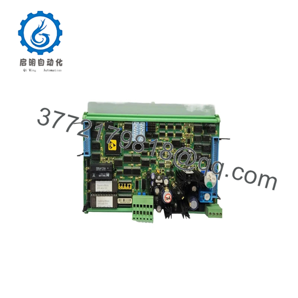
ZM411
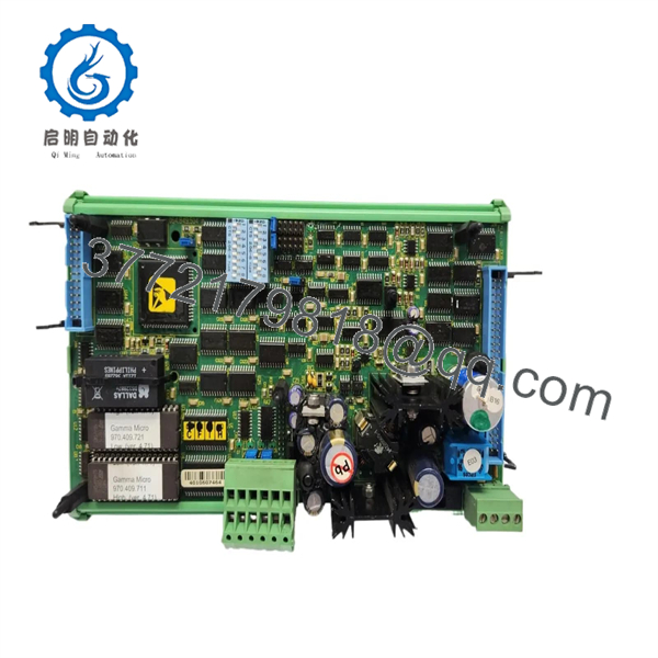
ZM411
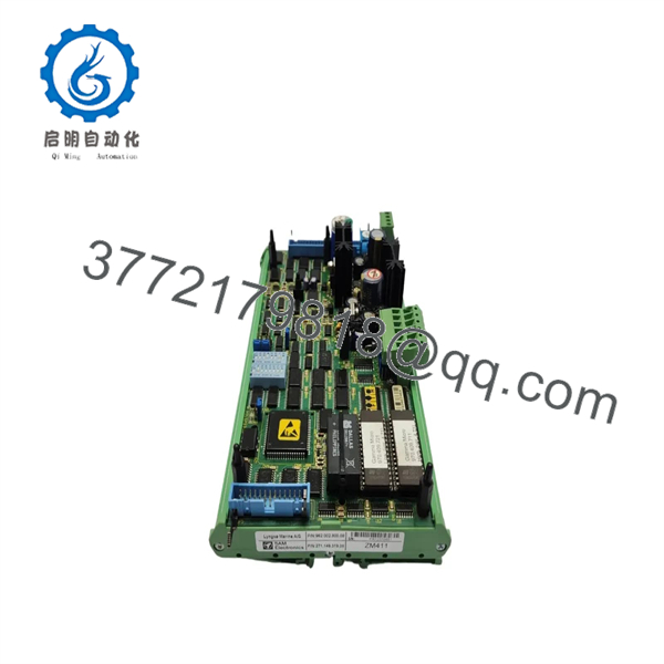
ZM411
Firmware/Software Versions & Upgrade Notes
- Firmware Synchronization: The relies on socketed EPROM/EEPROM chips or flash memory carrying specific system firmware versions (e.g., DMS 2100 software build). Verify that the firmware revision on the new card matches your system’s software architecture.
- Hardware Compatibility: The card is pin-compatible with SAM Electronics and Lyngsoe Marine GAMMA MICRO rack slots. Ensure node addressing DIP switches are configured identically to the failed module before system start.
- System Logic Preservation: Application logic and parameter databases are maintained across the central bus or stored in onboard non-volatile memory. Do not attempt firmware upgrades during a hardware swap unless advised by qualified field support.
Frequently Asked Questions (FAQ)
Q: Is this SAM Electronics module guaranteed to be Brand New Surplus?
Yes. This product is a Brand New Surplus unit. It is not used, not pulled from a decommissioned vessel, and not refurbished. All modules undergo rigorous quality verification to ensure OEM-level reliability.
Q: What systems primary use the SAM Electronics / Lyngsoe Marine CPU card?
The is deployed in marine bridge maneuvering systems, main engine remote control panels (DMS 2100 / DMS 2000), and integrated engine room alarm and monitoring systems (UMS 2100 / MCS 2200).
Q: Why should we avoid refurbished or pulled cards for marine application?
Shipboard control systems experience continuous vibration, humidity, and wide thermal variations. Used or refurbished cards frequently suffer from dried electrolytic capacitors, degraded solder points, and latent corrosion that lead to intermittent CPU resets and unexpected propulsion loss.
Q: Do I need specialized external programming tools to replace a module?
In most standard direct-replacement scenarios, no specialized programming software is required. Setting the hardware DIP/jumper configurations to match the existing card allows the module to handshake cleanly with adjacent I/O modules upon power-up.
Q: What warranty coverage is included with this New Surplus card?
We back this New Surplus module with a comprehensive 1Year functional replacement warranty, providing complete operational confidence for marine engineers, vessel managers, and automation integrators.



