
 WhatsApp: +86 16626708626
 Email:
  Phone: +86 16626708626
Description
3. Key Technical Specifications
| Parameter | Value |
|---|---|
| Model Number | VS3034 A001 |
| Brand | Sam Electronics AG |
| Series | VS3000 Marine Control |
| Product Type | Vessel Control System Module |
| Power Supply | 24 VDC nominal (18-32 VDC range) |
| Power Consumption | 15 W typical |
| Operating Temperature | -15°C to +55°C |
| Storage Temperature | -25°C to +70°C |
| Protection Rating | IP20 (chassis) |
| Communication Protocols | Sam Marine Bus, Modbus RTU |
| Mounting | DIN rail or backplane |
| Certifications | DNV-GL, ABS type approved |
4. Product Introduction
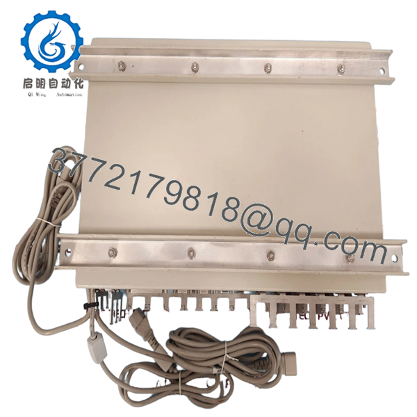
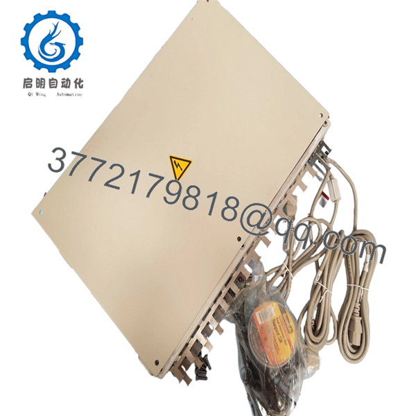
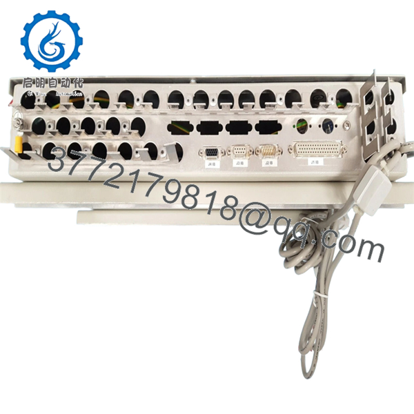
The Sam Electronics VS3034 A001 is a marine automation module belonging to the VS3000 series, typically deployed in vessel control systems for propulsion management and thruster interfaces. This unit integrates with Sam Electronics DCS platforms to provide local control logic and signal conditioning for main engines and bow/stern thrusters.
Field experience indicates the VS3034 A001 is often found in engine control room cabinets as part of a distributed I/O network. It handles discrete and analog signals from propulsion controls. The A001 revision includes specific firmware for particular vessel configurations.

- VS3034 A001
5. Installation & Configuration Guide
Total estimated time for trained technician: 20-30 minutes
Stage 1: Pre-Installation Preparation (5 minutes)
⚠️ Safety First: Notify the bridge and engine control room (ECR). Isolate the 24VDC supply feeding the module. Lock-out/tag-out (LOTO) if the cabinet contains live bus bars. Wait 2 minutes for internal capacitors to discharge.
Tools Required:
- ESD wrist strap
- Small flathead screwdriver (3mm)
- Multimeter
- Wire labels
- Smartphone for photos
Documentation:
- Photograph all wiring connections.
- Label each wire with its terminal number.
- Note the physical location in the rack (slot number).
Stage 2: Removing the Old Module (5 minutes)
- Remove the front cover if present.
- Photograph the LED status (if the unit is failed but still powered).
- Disconnect wiring one terminal at a time. Keep the labels attached.
- Release DIN rail locking clip or backplane latches.
- Slide the module upward or pull straight out.
⚠️ Keep the old module for reference until the new one is running.
Stage 3: Installing the New Module (8 minutes)
- ESD prep: Grounded wrist strap. Work on an ESD mat.
- Inspect the new unit:
- Verify model: VS3034 A001 exactly.
- Check for physical damage or bent pins.
- Configure DIP switches/jumpers (Critical):
- Replicate the exact settings from the photo of the old module.
- Node address and baud rate settings are critical for bus communication.
- Mount the module:
- For DIN rail: tilt top in, push bottom until it clicks.
- For backplane: align guides and push until latches engage.
- Reconnect wiring following the photo exactly. Torque terminals to 0.5 Nm.
Self-Checklist:
- DIP switches match the old unit
- Wiring matches the photo
- Module seated and locked
- No stray wire strands
Stage 4: Power-On & Testing (7 minutes)
Pre-Power Check:
- Multimeter on DC range. Measure at terminals: 22-26 VDC.
- No short between +24V and ground.
Power-On Steps:
- Close the 24VDC breaker.
- Observe LEDs:
- Green PWR LED = power OK
- Green RUN LED = module operating
- Red ERR LED = fault condition
- Verify communication with the main controller (check the master CPU for “Module Online” status).
- Test discrete inputs by toggling the corresponding field devices.
- Monitor analog inputs for correct scaling.
⚠️ Troubleshooting:
- Red ERR LED solid: Possible configuration mismatch. Verify node address and baud rate.
- No communication: Check bus termination resistors. Measure bus voltage (typically 2-5V on RS-485).
- Incorrect analog readings: Verify the input range matches the sensor (4-20mA vs 0-10V).
6. Frequently Asked Questions (FAQ)
Q1: Can I hot-swap this module?
A: No. The VS3034 A001 is not designed for hot-swap. Remove 24VDC power before installation to prevent damage to the backplane or adjacent modules.
Q2: Is this module obsolete?
A: The VS3000 series is considered legacy by Sam Electronics. We stock new original surplus units. No factory warranty or technical support from Sam Electronics is available. We provide our own testing and 1-year warranty.
Q3: What is the direct replacement?
A: Sam Electronics recommends the VS4000 series equivalents for new installations, but retrofitting requires a system upgrade. Contact us for retrofit adapter solutions.
Q4: Will I lose configuration when I replace it?
A: The VS3034 A001 does not store the main application program. However, if it uses onboard DIP switches or jumpers, those settings will be lost if not replicated. Take a clear photo before removal.
Q5: Why is there no detailed datasheet available?
A: Sam Electronics restricted detailed documentation for the VS3000 series to authorized service partners. Our specifications are compiled from field measurements and maintenance records. Verify pinouts with your vessel’s OEM wiring diagram before installation.
Q6: Do you test these units before shipping?
A: Yes. Every VS3034 A001 undergoes functional testing including power-on verification, communication loopback, and 2-hour burn-in. A test report is included with the shipment.


