
 WhatsApp: +86 16626708626
 Email:
  Phone: +86 16626708626
Description
Key Technical Specifications
| Parameter | Specification |
|---|---|
| Manufacturer | SAM Electronics / Lyngsø Marine |
| Model | EMP-2200M |
| Part Number | 815.001.200.01 |
| Product Type | Engine Manoeuvring System / marine engine control unit |
| Primary Application | Ship main-engine control and monitoring |
| System Category | Engine Control & Alarm / Marine Automation |
| Operator Interface | Display and dedicated control keys |
| Control Functions | Main-engine operating commands and status monitoring |
| Alarm Functions | Alarm indication and acknowledgement functions |
| Operating Modes | System-dependent; bridge/local/emergency modes are reported for this configuration |
| Power Supply | Verify from the vessel-specific documentation before energization |
| Communication | Verify connector and bus configuration against the installed system |
| Firmware / Configuration | Must be matched to the vessel’s installed control architecture |
| Replacement Part Number | 815.001.200.01 |
Supplier documentation consistently links EMP-2200M / 815.001.200.01 with SAM Electronics–Lyngsø Marine’s Engine Manoeuvring System. Listings describe the unit as a marine main-engine control/operation panel used for monitoring, alarm handling, and engine-control functions.
There is conflicting aftermarket technical data for electrical ratings and internal architecture. One supplier describes the same part as a 220 VAC CPU with Ethernet and RS-485 interfaces, while other sources identify it as an engine manoeuvring/control panel. Those detailed electrical specifications should not be treated as verified OEM specifications without the original SAM documentation or a matching unit nameplate.
Product Introduction
The SAM Electronics EMP-2200M, part number 815.001.200.01, is a marine Engine Manoeuvring System component used for main-engine operation and monitoring. Supplier records identify it with SAM Electronics–Lyngsø Marine and place it within marine engine-control and alarm applications.
The unit provides an operator interface for engine status, alarms, operating commands, and control-mode functions. It is therefore relevant to maintenance and retrofit work on vessels using legacy SAM/Lyngsø Marine engine-control equipment. Because available aftermarket descriptions are not fully consistent, replacement should be based on the complete part number, physical configuration, vessel control-system architecture, and existing wiring rather than model name alone.
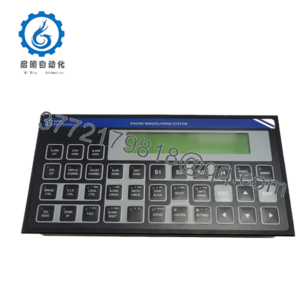
EMP-2200M
Installation & Configuration Guide
Stage 1 — Pre-Installation Preparation
Estimated time: 30–60 minutes for preparation, excluding vessel-specific shutdown and commissioning procedures.
- Place the main engine and propulsion-control system into the manufacturer’s approved maintenance state.
- Apply the vessel’s lockout/tagout and electrical isolation procedure.
- Confirm that remote, bridge, engine-room, and emergency control stations cannot issue unintended commands during maintenance.
- Record existing alarms, operating-mode status, and relevant control parameters.
- Photograph the installed EMP-2200M and all connected cables before disconnection.
- Record the exact part number and revision markings.
- Compare the replacement unit with the existing unit before removing anything.
⚠️ Do not assume the supply voltage from third-party listings. Published records conflict on whether this exact assembly should be treated as a 220 VAC processor module or a marine control-panel assembly with a different supply arrangement. Verify the vessel wiring diagram and the nameplate of the installed/replacement unit first.
Stage 2 — Removing the Existing Module
- Confirm that the propulsion system is safely shut down.
- Isolate the relevant control-system power supplies.
- Verify absence of hazardous voltage with an appropriate meter.
- Label every connector and cable before removal.
- Photograph connector positions and cable routing.
- Release the panel’s mounting hardware according to the vessel’s equipment arrangement.
- Disconnect the connectors without pulling on individual wires.
- Remove the existing EMP-2200M carefully.
- Inspect connectors and surrounding wiring for:
- Corrosion
- Moisture ingress
- Loose terminals
- Bent contacts
- Damaged insulation
- Evidence of overheating
- Retain the original unit until the replacement has passed commissioning.
Stage 3 — Installing the New Module
- Wear appropriate ESD protection when handling exposed electronic assemblies.
- Verify 815.001.200.01 exactly against the replacement identification label.
- Compare connector arrangement, mounting dimensions, display arrangement, keys, and revision markings with the removed unit.
- Inspect all connectors before installation.
- Install the unit in the original mounting position.
- Reconnect cables according to the photographs and vessel wiring documentation.
- Confirm that each connector is fully seated and mechanically retained.
- Verify protective earth and power connections according to the approved vessel wiring diagram.
- Check communication or system-bus connections where fitted.
- Confirm that no cable is pinched or under excessive mechanical tension.
⚠️ Do not change pin assignments or jumper settings based on an online listing. If the replacement revision differs from the original, obtain the applicable SAM/Lyngsø Marine documentation before energizing the equipment.
Stage 4 — Power-On & Testing
- Complete a final wiring and mechanical inspection.
- Confirm that all personnel are clear of moving machinery.
- Restore power according to the vessel’s approved commissioning procedure.
- Observe the display, indicators, and startup behavior.
- Check for active or newly generated system alarms.
- Confirm communication with the associated engine-control system.
- Verify the selected operating mode.
- Test indication functions before issuing engine commands.
- Perform controlled command checks for the functions permitted by the vessel’s commissioning procedure.
- Confirm that bridge, local, and emergency control functions operate correctly where those modes are part of the installed configuration.
- Record final alarm status and configuration.
- Return the propulsion system to normal operation only after the responsible engineer approves the test results.
⚠️ A successful display startup does not by itself prove that the complete engine-control chain is healthy. Verify communication, command paths, feedback signals, alarms, interlocks, and control authority during commissioning.
Frequently Asked Questions (FAQ)
What is the SAM EMP-2200M?
The , part number 815.001.200.01, is identified by multiple marine automation suppliers as a SAM Electronics–Lyngsø Marine Engine Manoeuvring System component for ship main-engine control and monitoring.
Is a DCS processor or an engine control panel?
Available aftermarket sources conflict. One listing describes it as a marine DCS processor, while several independent marine-equipment listings identify the exact same part number as an Engine Manoeuvring System/control panel.
For procurement, the safest identification is SAM Electronics , P/N 815.001.200.01, followed by physical and system-level verification.
Is obsolete?
The available sources establish that it is a legacy marine automation component, but they do not provide sufficiently authoritative OEM lifecycle documentation to state a definitive discontinuation date. Some suppliers currently offer new-surplus, refurbished, or tested-used units.
Can I replace directly?
Only after confirming the complete part number, hardware revision, connector arrangement, vessel-specific configuration, and control-system compatibility. A physically similar marine controller should not be treated as a direct replacement without documentation.
What condition is available for ?
Market listings show several conditions, including new, new-surplus, refurbished, and tested-used units. One marine supplier specifically lists a tested-and-verified used unit, while another states that new and refurbished units can be supplied. Confirm the actual serial number, condition, test scope, and warranty for the individual unit being purchased.
What should I provide when sourcing a replacement?
Provide the complete / 815.001.200.01 identification, photographs of the nameplate and connectors, hardware revision, vessel/control-system information, and the reason for replacement. If possible, include the existing wiring diagram and photographs of the installed panel.
Should I replace the when the engine-control system reports a communication fault?
Not automatically. First check power supply, connectors, communication wiring, grounding, network/bus termination where applicable, configuration, and the associated controller. A communication alarm can originate elsewhere in the control path and does not by itself prove that the has failed.



