
 WhatsApp: +86 16626708626
 Email:
 Phone: +86 16626708626
Description
Key Technical Specifications
| Parameter | Value |
|---|---|
| Catalog number | P30B04010PCKST |
| Full model marking | P30B04010PCKSTA01 REV.C |
| Brand | Sanyo Denki |
| Series | BL Super P3 / P3 Super BL |
| Motor type | AC brushless servo motor |
| Rated output | 100 W |
| Rated speed | 3000 min⁻¹ |
| Maximum speed | 4500 min⁻¹ |
| Rated torque | 0.32 N·m |
| Continuous stall torque | 0.98 N·m |
| Maximum stall torque | 2.2 N·m |
| Instantaneous maximum current | 7.4 Arms |
| Torque constant | 0.162 N·m/Arms |
| Phase resistance | 1.58 Ω |
| Power rate | 22.0 kW/s |
| Electrical time constant | 1.3 ms |
| Mechanical time constant | 0.8 ms |
| Flange size | 40 mm or 42 mm square flange |
| Shaft diameter | 8 mm |
| Holding brake | Equipped |
| Brake voltage | 24 V |
| Rated current | 2.7 A |
| Supply class | 100 V AC class |
The P30B04010PCKST is a compact 100 W Sanyo Denki brushless servo motor with an integrated 24 V holding brake. Its rated point is 0.32 N·m at 3000 rpm, while the motor can deliver up to 2.2 N·m momentary stall torque.
Product Introduction
The Sanyo Denki P30B04010PCKST is a BL Super P3 AC servo motor intended for compact positioning axes, indexing tables, pick-and-place mechanisms, and light conveyor drives. It combines a 100 W continuous rating with an integrated holding brake for vertical-axis and load-retention applications.
This model is commonly selected as a direct replacement in existing Sanyo Denki servo systems because it preserves the original 40/42 mm flange, 8 mm shaft, 100 V-class electrical interface, and 24 V brake configuration. Verify the full suffix, encoder type, shaft/keyway detail, and connected SANMOTION amplifier compatibility before ordering.
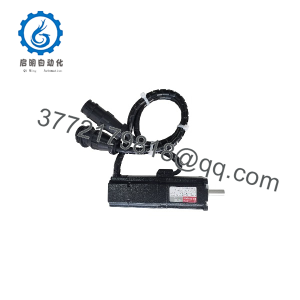
P30B04010PCKST
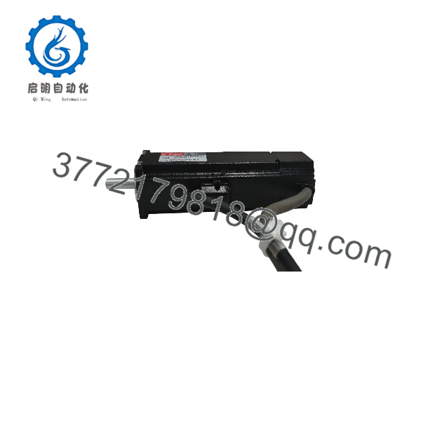
P30B04010PCKST
Installation & Configuration Guide
Stage 1: Pre-Installation Preparation
Estimated time: 15 minutes.
- ⚠️ Disable the servo drive, remove machine motion authority, and apply lockout/tagout to the drive and axis power circuits.
- Wait at least 5 minutes for drive bus capacitors to discharge; measure the DC bus before touching power terminals.
- Secure any vertical load with a mechanical stop, chain, or support fixture before releasing the brake.
- Prepare an ESD wrist strap, torque wrench, hex keys, multimeter, feeler gauge, coupling alignment tools, and camera.
- Photograph the motor label, encoder connector, brake connector, cable routing, coupling, and mounting orientation.
- Record the amplifier model, encoder type, pulse/analog command configuration, and servo parameters.
⚠️ Never release a holding brake on an unsupported vertical axis. The load can fall immediately.
Stage 2: Removing the Old Motor
Estimated time: 15–20 minutes.
- Confirm the servo drive is OFF and the DC bus voltage is below the safe-service threshold.
- Disconnect the motor power, encoder, and brake connectors; label each connector and wire route.
- Measure and record brake resistance before disconnection if the original brake circuit is suspected.
- Support the motor and remove the coupling setscrew or clamp.
- Remove the four flange-mounting screws while supporting the motor weight.
- Withdraw the motor straight from the mounting face to avoid bending the shaft or damaging the encoder.
- Inspect the coupling, mounting face, shaft bore, keyway, and cable glands for wear or misalignment.
⚠️ Keep the old motor until the replacement has completed a full jog, homing, and load test.
Stage 3: Installing the New Motor
Estimated time: 15–20 minutes.
- Verify the replacement is P30B04010PCKST, preferably with matching A01 REV.C identification and encoder configuration.
- Put on an ESD wrist strap before handling connectors.
- Mount the motor to the machine flange using the original screw size and torque specification.
- Install and align the coupling; verify concentricity and axial clearance according to the coupling manufacturer’s limits.
- Reconnect the motor power, encoder, and 24 V brake connectors using the original labels.
- Confirm brake wiring polarity and that the brake releases only when the drive applies the commanded 24 V.
- Check that cables have adequate bend radius and are secured away from moving parts.
Self-checklist:
- Motor model and revision match
- Encoder connector fully seated
- Brake connector and 24 V supply verified
- Coupling aligned and secured
- Flange screws torqued
- Cables dressed and strain-relieved
Stage 4: Power-On & Testing
Estimated time: 20–30 minutes.
- ⚠️ Before enabling the drive, verify motor-power phase continuity, encoder feedback, brake wiring, and protective earth continuity.
- Power the servo drive and confirm there are no encoder, overcurrent, overload, or brake alarms.
- Set the drive to a low-speed jog mode with the load mechanically safe.
- Release the brake and jog the axis in both directions at reduced speed.
- Verify correct direction, encoder feedback, positioning direction, and limit-switch response.
- Perform homing and a controlled dry-cycle test.
- Restore normal gain, acceleration, and motion parameters only after confirming stable operation.
⚠️ If the motor overheats, stalls, or produces an encoder alarm, stop immediately. A mismatched encoder, incorrect motor-power phasing, or wrong brake wiring can damage the motor or drive.
Frequently Asked Questions (FAQ)
Can I hot-swap the P30B04010PCKST?
No. Shut down the servo drive, wait for the DC bus to discharge, and disconnect all motor, encoder, and brake wiring before removal.
Does this motor include a holding brake?
Yes. The P30B04010PCKST includes a 24 V holding brake, which is useful for vertical axes and applications requiring load retention after drive power is removed.
What is the rated torque and speed?
The motor is rated for 0.32 N·m at 3000 rpm and 100 W continuous output. Its maximum speed is 4500 rpm.
Can I use it with any Sanyo Denki servo amplifier?
No. Match the motor to the correct SANMOTION or legacy Sanyo Denki amplifier, encoder interface, and command configuration. Verify the amplifier catalog number and parameter set before substitution.
Is this motor obsolete?
The BL Super P3 platform is legacy Sanyo Denki motion-control hardware. New-original stock is limited; suppliers commonly offer new surplus or tested refurbished units.
Will the encoder settings transfer automatically?
No. The drive must recognize the connected encoder and correct axis parameters. Back up the amplifier parameters first, then verify encoder type, direction, homing method, and gains after installation.
Why is the price lower than a new OEM motor?
Because this is discontinued or limited-availability legacy stock. Pricing reflects condition, testing, warranty exposure, encoder configuration, and the difficulty of matching the exact motor suffix and revision.



