
 WhatsApp: +86 16626708626
 Email:
  Phone: +86 16626708626
Description
Key Technical Specifications
| Parameter | Value |
|---|---|
| Model | DL22N-22 |
| Manufacturer | SCHIELE / Entrelec |
| Product Type | Power contactor |
| Coil Voltage | 24 VAC |
| Coil Frequency | 60 Hz |
| Main Contact Configuration | 3-pole |
| Auxiliary Contacts | 2 NO / 2 NC |
| AC-3 Motor Rating | 22 kW at 400 V AC |
| Rated Operational Voltage | Up to 690 V AC |
| Rated Operational Current | 44 A class for 22 kW motor switching |
| Rated Thermal Current | 55 A open / 50 A enclosed at 55 °C |
| Mechanical Life | Up to 10 million operations |
| Operating Temperature | -25 °C to +55 °C |
| Storage Temperature | -50 °C to +80 °C |
| Mounting Position | Vertical mounting plane, ±22.5° |
| Auxiliary Contact Rating | 6 A at 230/400 V AC-15 |
| Coil-to-Contact Isolation | Safety isolation up to 400 V AC |
| Insulation Voltage | 690 V IEC / 750 V VDE |
| Manufacturer Status | Discontinued |
The SCHIELE/Entrelec technical documentation identifies the DL N family as contactors for three-phase motor and AC-load switching. It specifies AC-3 applications for squirrel-cage motors and gives a 22 kW motor example for the DL 22 N size.
The exact -22 configuration is also documented in market listings as a 24 VAC, 60 Hz, 3-pole contactor with 2 NO auxiliary contacts; therefore, the coil voltage should be checked against the nameplate before replacing an installed unit.
Product Introduction
The SCHIELE DL22N-22 is an electromechanical three-phase power contactor intended for switching motors and other AC loads. The DL 22 N frame is rated for motor applications up to 22 kW at 400 V AC under AC-3 duty, with the -22 version commonly identified with a 24 VAC, 60 Hz coil and 2 NO auxiliary contacts.
Its application value is straightforward: it provides electrically controlled switching between an automation system and a higher-power AC load. The contactor supports auxiliary feedback/control circuits and is designed for industrial motor-starting applications. The manufacturer documentation specifies forced contact opening, defined switching characteristics, and mechanical life up to 10 million operations for the applicable contactor family.
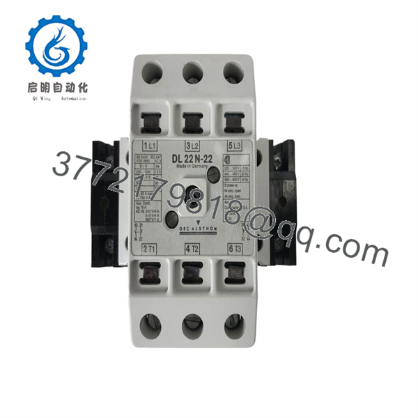
DL22N-22
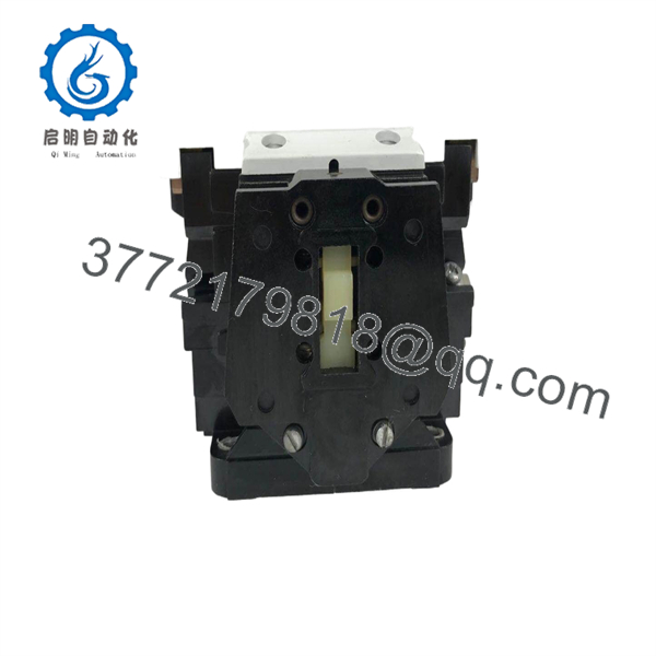
DL22N-22
Installation & Configuration Guide
Stage 1 — Pre-Installation Preparation
- Confirm that the replacement is DL22N-22, not another DL N frame or a different coil-voltage variant.
- Verify the coil marking. The
-22configuration is commonly listed as 24 VAC, 60 Hz; do not energize the coil until the installed unit’s nameplate has been checked. - Isolate the incoming power and apply the site’s lockout/tagout procedure.
- Verify absence of voltage with a properly rated meter.
- Record existing wiring, auxiliary-contact usage, and terminal designations before removal.
- Prepare insulated screwdrivers, a torque-controlled driver, multimeter, and appropriate PPE.
- Confirm that the motor protection device and upstream short-circuit protection are correctly sized for the actual motor and application.
Stage 2 — Removing the Existing Contactor
- De-energize both the main power circuit and the contactor control circuit.
- Verify zero voltage at the main and coil terminals.
- Photograph the existing terminal arrangement before disconnecting conductors.
- Label line, load, coil, and auxiliary-contact conductors.
- Remove the power and auxiliary wiring without disturbing adjacent devices.
- Release the contactor from its mounting arrangement.
- Inspect the mounting surface and conductors for heat damage, loose hardware, discoloration, or insulation deterioration.
Stage 3 — Installing the DL22N-22
- Verify the replacement nameplate and contact configuration before installation.
- Mount the contactor in the manufacturer’s specified orientation; the technical documentation specifies a vertical mounting plane with ±22.5° tolerance.
- Connect the three-phase supply and motor conductors to the corresponding main terminals.
- Reconnect the coil circuit only after confirming the actual coil voltage.
- Reconnect the 2 NO / 2 NC auxiliary circuits according to the original control schematic.
- Tighten terminals using the applicable manufacturer torque specification rather than relying on hand-tightening.
- Check conductor routing, phase identification, terminal clearance, and mechanical stability.
Stage 4 — Power-On & Testing
- Perform a final insulation, continuity, and wiring check before energization.
- Confirm that the contactor coil is receiving the correct control voltage.
- Energize the control circuit first where the machine design permits.
- Command the contactor and verify clean mechanical engagement.
- Confirm auxiliary-contact feedback in the PLC, relay logic, or control circuit.
- Energize the motor circuit and perform a controlled start.
- Check motor rotation, contactor noise, terminal heating, current balance, and overload behavior.
- If the contactor chatters, fails to pull in, or drops out unexpectedly, immediately check coil voltage, control-circuit wiring, terminal tightness, and the actual coil specification.
Frequently Asked Questions
Q1. Is the SCHIELE DL22N-22 a PLC or control module?
No. It is an electromechanical power contactor used to switch AC loads, particularly three-phase motors. Listings that describe this model as a PLC or general-purpose control module are inconsistent with the SCHIELE/Entrelec contactor documentation.
Q2. What is the motor rating of the DL22N-22?
The DL 22 N frame is associated with a 22 kW three-phase motor at 400 V AC under AC-3 duty. Actual selection must also account for motor current, duty cycle, switching frequency, and ambient conditions.
Q3. Is the coil 24 VAC?
The exact is currently listed by multiple industrial-parts sources as 24 VAC, 60 Hz. However, older SCHIELE/Entrelec contactors were available with multiple coil-voltage codes, so the physical nameplate should be treated as the final authority for a replacement.
Q4.he discontinued?
Yes. Current industrial-parts listings identhe as discontinued by the manufacturer, although surplus and used units remain available through secondary-market suppliers.
Q5. Can I replace another contactor directly a ?
Only if the coil voltage, contact arrangement, terminal layout, AC-3 rating, auxiliary contacts, and mounting dimensions all match. Do not treat the frame designation alone as proof of interchangeability.
Q6. Does the contactor include overload protection?
The contactor itself is a switching device; motor overload protection is normally provided by a correctly selected overload relay or equivalent protective device. The manufacturer documentation discusses compatible thermal overload arrangements separately.
Q7. Shoulded be accepted for a critical replacement?
Condition should be verified individually. For a used unit, inspect the contacts and housing, verify coil operation, measure contact continuity, inspect auxiliary contacts, and perform a functional switching test before installation. Market listings show both used and unused-surplus examples, so condition cannot be assumed from the model number alone.



