
 WhatsApp: +86 16626708626
 Email:
  Phone: +86 16626708626
Description
Key Technical Specifications
- Manufacturer: Schneider Electric
- Part Number: 140ACI03000
- Product Family: Modicon Quantum
- Module Type: Eight-channel unipolar analog input module
- Number of Inputs: 8 differential channels
- Supported Input Ranges: 1–5 V DC voltage input; 4–20 mA current input
- Mixed Signal Capability: Mixed voltage and current inputs supported by channel, using the required input-to-sense jumpers for current-input measurement
- Input Resolution: 12 bits
- Quantum Addressing Requirement: 9 input words
- Voltage Input Impedance: Greater than 20 MΩ
- Current Input Impedance: 250 Ω ±0.03%
- Maximum Voltage Input: 50 V DC
- Maximum Current Input: 25 mA
- Accuracy at 25 °C: Typical ±0.05% of full scale; maximum ±0.1% of full scale
- Current-Mode Accuracy Addition: Add ±0.03% to the voltage-mode accuracy specification
- Linearity Error: ±0.04%
- Temperature Drift: Typical ±0.0025% FS/°C; maximum ±0.005% FS/°C
- Input Filter: Single-pole low-pass filter, −3 dB at 15 Hz ±20%
- Common-Mode Rejection: Better than −72 dB at 60 Hz
- Channel-to-Bus Isolation: 1,000 V DC; 3,000 V peak-to-peak for 1 minute
- Maximum Channel-to-Channel Operating Voltage: 30 V DC
- Update Time: 5 ms for all eight channels
- Fault Detection: Broken-wire detection in 4–20 mA mode; undervoltage detection in 1–5 V mode
- Local Indicators: 8 green channel-on LEDs, 8 red channel-fault LEDs, 1 green active/bus LED, and 1 red external-fault LED
- Bus Current Requirement: 240 mA
- Power Dissipation: 2 W
- External Field Power: Not required by the module
The 140ACI03000 is Schneider Electric’s Modicon Quantum 8-input multirange analog-input module. The manufacturer product page identifies the module as “8 I multirange,” while Quantum documentation specifies its differential 1–5 V DC and 4–20 mA inputs, 12-bit resolution, 5 ms update time, and 9-word input addressing.
Product Introduction
The Schneider Electric 140ACI03000 is an eight-channel differential analog input module for Modicon Quantum PLC racks. It converts field signals from 1–5 V DC transmitters and 4–20 mA loops into Quantum controller data for process measurement, monitoring, and alarm logic. It supports mixed voltage and current use when the required current-input jumpers are installed.
This module fits legacy Quantum systems that need a direct eight-point analog-input replacement without changing the controller or I/O architecture. Its 5 ms all-channel update, 12-bit resolution, broken-wire detection for current loops, and 3,000 V peak-to-peak channel-to-bus isolation make it suited to standard process instrumentation.
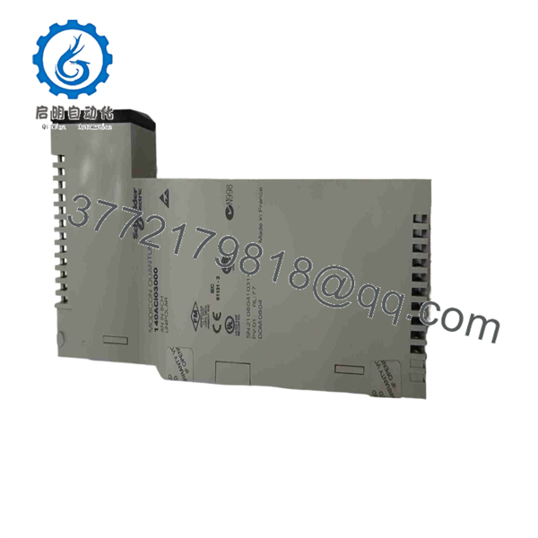
140ACI03000
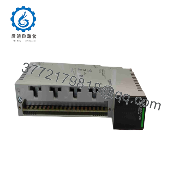
140ACI03000
Troubleshooting Quick Reference
| Symptom | Possible Cause | Relevance to This Part | Quick Check Method | Recommendation |
|---|---|---|---|---|
| All eight analog values read zero or invalid | Quantum rack power loss, module not seated, backplane communication fault, controller configuration error, or failed module | ✅ Medium | Check the module’s green Active LED. Verify the Quantum rack power supply and controller run status. With power removed, reseat the module and inspect the backplane connector for bent or recessed contacts. Confirm the configured I/O address and module type in the PLC project. | Check rack power, module seating, and configuration before replacing the 140ACI03000. A dead Active LED often points to a rack or backplane issue. |
| One 4–20 mA channel reads 0 mA or reports a fault | Open transmitter loop, blown field fuse, broken wire, incorrect terminal connection, no loop power, or failed channel | ✅ Medium | Measure loop current in series or measure voltage across the module’s 250 Ω current input, following the wiring diagram. A healthy 4–20 mA loop produces approximately 1–5 V across 250 Ω. Check transmitter supply and cable continuity. | Repair the field loop first. The module’s broken-wire diagnostic can flag an open 4–20 mA circuit, so a channel-fault LED does not automatically mean the card is bad. |
| One 1–5 V channel reads low or shows underrange | Sensor/transmitter failure, missing sensor supply, signal return open, incorrect common reference, or module channel issue | ✅ Medium | Measure the voltage directly at the channel input and sense terminals using a high-impedance meter. Compare it with the PLC raw value and a known-good channel. Verify the signal is within 1–5 V DC. | Correct the transmitter, reference, or field wiring before replacing the module. |
| All current channels read incorrectly after installation | Current-input jumpers missing, installed in the wrong position, incorrect terminal wiring, or wrong PLC scaling | ✅ High | De-energize the field circuit as required. Verify that each current-input channel has the OEM-required jumper installed between its input and sense terminals. Confirm the PLC application uses 4–20 mA scaling, not 1–5 V scaling. | Install or correct the jumpers and configuration. This is one of the most common commissioning errors with the 140ACI03000. |
| Current inputs are correct but voltage inputs are wrong | Incorrect signal reference, wiring error, input range configuration issue, damaged signal cable, or transmitter fault | ✅ Medium | Measure each voltage source at the module terminals. Verify signal and sense wiring against the Quantum terminal-block diagram. Compare raw counts with a calibrated 1–5 V signal source if available. | Check terminal wiring and source reference before replacing the card. Do not share returns incorrectly across differential inputs. |
| Reading is noisy or unstable | Poor shield termination, ground loop, nearby VFD noise, loose terminal, unstable transmitter, or damaged cable | ❌ Low to Medium | Check the signal at the transmitter and at the module with a meter. Inspect shield termination according to site practice and the installation manual. Verify grounding at one intended point where required. Compare against the module’s 15 Hz input-filter behavior. | Correct the instrument loop, grounding, and cable routing. Keep analog wiring separated from motor leads, contactor wiring, and high-current conductors. |
| Red external-fault LED is on | One or more channel faults, broken current loop, voltage underrange, external wiring problem, or module fault | ✅ Medium | Identify which red channel-fault LED is active. Check that channel’s field signal, jumper, wiring, transmitter power, and range selection. Review PLC diagnostics for the channel state. | Fix the external channel issue first. The external-fault indicator summarizes field-side problems and does not prove the module has failed. |
| Values freeze or update slowly | PLC scan issue, communication problem, application logic, online-force condition, or controller fault | ❌ Low | Confirm changing field input values with a meter, then compare raw input data in the controller with the HMI value. Check controller health, scan time, and any forces or scaling blocks. | The module updates all channels in 5 ms. If raw data changes but the HMI does not, the problem is likely in PLC logic or HMI communications. |
| New module shows incorrect values on several channels | Wrong module type in configuration, terminal block mismatch, current jumpers omitted, swapped field wires, or scaling mismatch | ✅ High | Compare the old and new part numbers. Verify the terminal block and field wiring. Confirm all current-channel jumpers. Check the PLC configuration uses 140ACI03000 and validate raw counts with a known signal source. | Do not force calibration. Quantum documentation states calibration is not required for this module. Correct wiring and configuration first. |
❗ Current-input warning: The module requires jumpers between the input and sense terminals for 4–20 mA channels. Missing jumpers produce bad readings that can look exactly like a failed analog card. Take a photo of the old terminal arrangement before removing it.
❗ Scaling warning: A 4–20 mA signal across the module’s 250 Ω current input corresponds to roughly 1–5 V. Verify both the field wiring and PLC scaling before condemning the module.
❗ Grounding warning: Do not wire analog signals from memory. Differential inputs reduce common-mode problems, but incorrect return or shield treatment can still produce unstable values. Keep analog cables away from VFD output conductors and high-current switching circuits.
❗ Replacement warning: Confirm that the replacement is exactly 140ACI03000. Schneider also lists the similarly named 140ACI03000C as discontinued and points toward a Modicon X80 migration option; that does not mean it is a plug-in replacement for a Quantum rack.
If you are stuck, send technical support clear photos of the module, terminal block, current-input jumpers, LED state, PLC diagnostics, raw input words, field signal measurements, and the Quantum rack model. Keep these checks in mind and you will save yourself 90% of typical rework time.
Frequently Asked Questions (FAQ)
What signals does the Schneider 140ACI03000 accept?
The 140ACI03000 accepts eight differential analog inputs. Each channel can measure either 1–5 V DC or 4–20 mA. The module supports mixed current and voltage use, but current-mode channels require the specified jumper between the input and sense terminals.
Can I mix 4–20 mA and 1–5 V inputs on the same module?
Yes. The Quantum documentation describes the 140ACI03000 as accepting mixed current and voltage inputs. Configure and wire each channel correctly, and install the required input-to-sense jumper for every channel used in 4–20 mA current mode. Do not install the jumper on a voltage-input channel unless the OEM wiring documentation instructs you to do so.
Does the 140ACI03000 need external field power?
No external power supply is required by the module itself. That does not mean your transmitters do not need power. Two-wire 4–20 mA transmitters still require their own loop supply, typically from the plant’s instrument-power system.
How many Quantum input registers does it use?
The 140ACI03000 requires nine contiguous Quantum input words. Eight words carry channel data, and the remaining word supports status or diagnostic information according to the Quantum hardware reference documentation.
Can I hot-swap the 140ACI03000?
Do not assume hot swapping is safe without verifying your Quantum rack, power supply, site procedures, and process risk. Removing an analog module may disrupt live process values, trigger alarms, or cause the controller to act on bad data. Put the process into a safe state, document the terminal wiring and current jumpers, and follow your approved maintenance procedure before removal.
Does the module require calibration after replacement?
No. The Modicon Quantum hardware reference states that calibration is not required for the 140ACI03000. If values are incorrect after a swap, check channel wiring, current jumpers, transmitter output, PLC hardware configuration, and engineering-unit scaling before trying to compensate in software.
Is the 140ACI03000 obsolete, and what is the replacement?
The Modicon Quantum platform is a legacy product family, so surplus availability and repair support should be confirmed before committing to a maintenance plan. Schneider’s product information for the similarly designated 140ACI03000C marks that version as discontinued and identifies an eight-channel Modicon X80 isolated high-level analog-input module as a migration replacement. It is a migration path, not a direct plug-in Quantum rack replacement.
Why is a New Surplus 140ACI03000 cheaper than an OEM factory order?
New Surplus stock typically comes from unused project inventory, plant storerooms, distributor liquidation, canceled projects, or decommissioned Quantum-system spares. It can be original Schneider material, but it is outside normal factory supply and may have limited stock or unknown storage history.
A credible supplier should verify the exact 140ACI03000 label, inspect terminals and backplane contacts for damage or corrosion, confirm the module powers up in a genuine Quantum rack, check Active and fault LEDs, test all eight channels with calibrated 1–5 V and 4–20 mA sources, and issue a test report. Ask for actual photos, testing evidence, written warranty terms, confirmed stock quantity, and a ship date before placing the order.



