
 WhatsApp: +86 16626708626
 Email:
  Phone: +86 16626708626
Description
Key Technical Specifications
| Parameter | Value |
|---|---|
| Product Range | Modicon Quantum automation platform |
| Product Type | Analog input module |
| Number of Inputs | 16 |
| Input Type | Differential |
| Signal Ranges | 0–20 mA, 0–25 mA, 4–20 mA |
| Input Impedance | 250 Ω |
| Absolute Maximum Input | 30 mA |
| Accuracy | ±0.125% of full scale |
| Update Time | 15 ms, 2-wire / 4-wire |
| Addressing Requirement | 17 input words |
| Filter | Single-pole low-pass, −3 dB at 34 Hz ±25% |
| Common-Mode Rejection | > −90 dB at 60 Hz |
| Channel-to-Bus Isolation | 1,780 V AC for 60 s |
| Bus Current Requirement | 360 mA |
| Power Dissipation | 5 W |
| Operating Temperature | 0 to 60 °C |
| Storage Temperature | −40 to 85 °C |
| Relative Humidity | Up to 95%, non-condensing |
| Module Format | Standard |
| Net Weight | 0.3 kg |
| Fault Detection | Broken wire detection for 4–20 mA |
The resolution can be configured as 0–16,000 counts for 4–20 mA, 0–20,000 counts for 0–20 mA, 0–25,000 counts for 0–25 mA, or 0–4,095 counts for the alternate 4–20 mA range.
Product Introduction
The Schneider Electric 140ACI04000 is a 16-channel differential analog input module for the Modicon Quantum automation platform. It accepts 0–20 mA, 0–25 mA, and 4–20 mA current signals and maps them into Quantum input words for process control applications.
Its 15 ms update time, 250 Ω input impedance, 1780 V AC channel-to-bus isolation, and per-channel diagnostic indication make it suitable for existing Quantum installations where the original I/O architecture must be maintained. It is now a discontinued component, so compatibility and available stock should be checked before procurement.
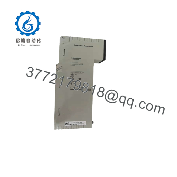
140ACI04000
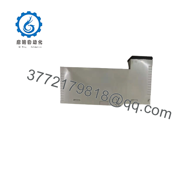
140ACI04000
Installation & Configuration Guide
Stage 1: Pre-Installation Preparation — Approximately 5–10 minutes
⚠️ Safety First: Put the controlled process into its approved safe state before removing the module. Follow the plant’s lockout/tagout procedure and verify that the rack is de-energized.
Tools Required:
- ESD wrist strap
- Appropriate screwdriver
- Digital multimeter
- Wire labels
- Smartphone or camera for configuration records
Before removing the existing module:
- Record the complete part number: 140ACI04000.
- Record the Quantum rack and slot location.
- Photograph the field wiring and terminal-strip arrangement.
- Record the existing I/O configuration and channel assignments.
- Document the signal range used by each channel.
- Save the current PLC application/configuration before hardware replacement.
- Check the replacement module for physical damage, corrosion, bent contacts, or missing components.
The 140ACI04000 uses a separate field-wiring terminal strip; Schneider documentation identifies the Modicon 140 XTS 002 00 terminal strip as a separately ordered component. Do not assume a replacement module includes the terminal strip.
Stage 2: Removing the Old Module — Approximately 5 minutes
- De-energize the Quantum rack according to the site’s shutdown procedure.
- Confirm the absence of hazardous voltage with an appropriate meter.
- Label field conductors if their identification is not already clear.
- Photograph the terminal wiring before disconnecting anything.
- Disconnect the field wiring without pulling on the conductors.
- Release the module’s mechanical retaining mechanism.
- Pull the module straight out of the rack.
- Inspect the rack connector and surrounding area for contamination or physical damage.
- Keep the removed module available until commissioning is complete.
⚠️ Do not wire the replacement from memory. A 16-channel analog module can look straightforward, but a single misplaced current-loop conductor can create an incorrect process value.
Stage 3: Installing the New Module — Approximately 5 minutes
- Put on the grounded ESD strap.
- Verify that the replacement is specifically Schneider Electric 140ACI04000.
- Compare the replacement module against the removed unit.
- Confirm that the Quantum rack slot is appropriate for the configured I/O.
- Insert the module carefully into the rack connector.
- Engage the module’s retaining mechanism.
- Reconnect the field wiring using the original documented terminal assignments.
- Check that every conductor is mechanically secure.
Self-Checklist:
- Correct 140ACI04000 model
- Correct Quantum rack and slot
- Field wiring matches photographs
- Terminal connections secure
- Module fully seated
- ESD precautions maintained
Stage 4: Power-On & Testing — Approximately 10–15 minutes
- Check the rack for wiring faults before energizing.
- Apply power according to the plant commissioning procedure.
- Check the module’s green bus-communication indication.
- Check the external-fault LED.
- Check the individual channel status/fault indicators.
- Confirm that the PLC recognizes the module at the expected rack/slot address.
- Verify the configured analog ranges.
- Check live values against known process values or a calibrated current source.
- Test representative 4–20 mA channels across the expected operating range.
- Confirm that broken-wire diagnostics behave as expected where 4–20 mA detection is configured.
The module provides one green bus-communication LED, one red external-fault LED, and individual green/red channel indicators.
⚠️ Important: Do not assume that a replacement 140ACI04000 is automatically equivalent to a newer X80 module. Schneider recommends BMXAMI0810 as the replacement, but it has eight inputs rather than sixteen. Migration therefore requires an I/O architecture and application review rather than a simple one-for-one physical substitution.
Frequently Asked Questions (FAQ)
Can I hot-swap the 140ACI04000?
Do not assume hot-swapping is permitted simply because the module is removable. Follow the Quantum hardware documentation and the site’s approved maintenance procedure for the specific rack configuration. For a planned replacement, de-energizing the rack is the conservative procedure.
Is the Schneider 140ACI04000 obsolete?
Yes. Schneider Electric identifies the 140ACI04000 as discontinued. The exact discontinuation date differs by regional Schneider website, while the U.S. listing gives December 31, 2022 and an end-of-standard-service date of December 31, 2030.
What is the recommended replacement?
Schneider Electric lists BMXAMI0810 as the recommended replacement. Be careful here: the BMXAMI0810 has 8 analog inputs, while the 140ACI04000 has 16. A replacement may therefore require additional modules and changes to the I/O configuration.
What current signals does the 140ACI04000 accept?
It supports 0–20 mA, 0–25 mA, and 4–20 mA input ranges. The module is a differential analog input design with a 250 Ω input impedance and a 30 mA absolute maximum input.
Will I lose my PLC program when replacing the analog input module?
Replacing an I/O module does not inherently mean that the PLC application is erased. The real concern is whether the replacement is recognized correctly by the existing Quantum hardware configuration and whether the channel configuration matches the original installation. Back up the application and document the existing I/O configuration before removing the module.
Is the 140ACI04000 suitable for 4–20 mA process instruments?
Yes. 4–20 mA is one of its supported input ranges, and the module provides broken-wire fault detection for 4–20 mA operation.
Why is an obsolete 140ACI04000 still available from surplus suppliers?
Legacy Quantum installations remain in service, so discontinued I/O modules can continue to circulate through surplus and industrial spare-parts channels. However, “available” does not automatically mean “new original.” Confirm whether the offered unit is factory sealed, new surplus, used, or refurbished, and request photographs of the actual module and its identification label before purchase. Schneider itself no longer treats the 140ACI04000 as a current commercial product.
Procurement note: For a critical plant spare, record the exact 140ACI04000 part number, existing hardware configuration, signal ranges, and module condition requirement on the purchase order. That prevents a visually similar Quantum analog module from being substituted incorrectly.



