
 WhatsApp: +86 16626708626
 Email:
  Phone: +86 16626708626
Description
Key Technical Specifications
| Parameter | Value |
|---|---|
| Manufacturer | Schneider Electric / Modicon |
| Part Number | 140CPS11420 |
| Product Family | Modicon Quantum automation platform |
| Product Type | AC-input power supply module |
| Power Supply Mode | Standalone or summable |
| Input Voltage, 115 V Range | 93–132 V AC, 47–63 Hz |
| Input Voltage, 230 V Range | 170–276 V AC |
| Input Current | 1.3 A at 115 V AC; 750 mA at 230 V AC |
| Inrush Current | 38 A at 115 V AC; 19 A at 230 V AC |
| Rated Input Power | 130 VA |
| Output Voltage | 5.1 V DC |
| Output Current, Standalone | 11 A at 60 °C |
| Output Current, Summable | 20 A at 60 °C |
| Associated Fuse | 2 A, slow-blow |
| Output Protection | Internal overload and overvoltage protection |
| Alarm Output | One normally closed contact, 6 A at 220 V AC power-supply fault rating |
| Local Indication | One green PWR OK LED |
| Power Dissipation | 6+1.5×Iout6 + 1.5 \times I_{out} W, with IoutI_{out} in A |
| Operating Temperature | 0 to 60 °C |
| Storage Temperature | −40 to +85 °C |
| Maximum Operating Altitude | 5,000 m |
| Relative Humidity | Up to 95%, non-condensing |
| Module Format | Standard Quantum module |
| Net Weight | Approximately 0.65 kg |
| Standards / Certifications | UL 508; CSA C22.2 No. 142; cUL; CE |
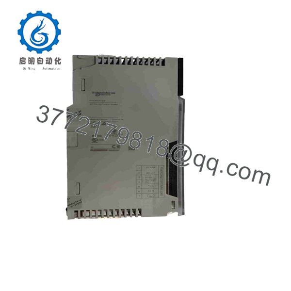
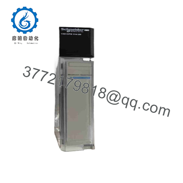
The Schneider Electric 140CPS11420 is a Modicon Quantum standard-format power-supply module with selectable 115/230 V AC input. It supplies 5.1 V DC at 11 A in standalone service or 20 A in summable service at 60 °C.
Product Introduction
The Schneider Electric 140CPS11420 is a 115/230 V AC power supply for Modicon Quantum PLC racks. It converts incoming AC power into regulated 5.1 V DC backplane power for Quantum controllers, I/O modules, and compatible rack hardware. It can operate as a standalone supply or as a summable supply where the Quantum rack architecture supports load sharing.
Use the 140CPS11420 when the installed Quantum system requires the exact AC-input supply and its backplane-current capacity. The module provides 11 A at 60 °C in standalone mode or 20 A at 60 °C in summable mode, plus internal overvoltage/overload protection, a green PWR OK LED, and a normally closed power-fault alarm contact.
140CPS11420
140CPS11420
Troubleshooting Quick Reference
| Symptom | Possible Cause | Relevance to This Part | Quick Check Method | Recommendation |
|---|---|---|---|---|
| Green PWR OK LED is off | No AC input, blown external fuse, incorrect input-range wiring, loose terminal connection, failed power supply, or failed rack connection | ✅ High | Apply lockout/tagout. Measure incoming AC voltage at the power terminal strip: confirm 93–132 V AC for the 115 V range or 170–276 V AC for the 230 V range. Inspect the 2 A slow-blow fuse and terminal tightness. | Verify input voltage, fuse condition, wiring, and rack connection before replacing the module. |
| PWR OK LED flashes or drops out under load | Rack current exceeds capacity, loose AC input, thermal overload, failing supply, poor backplane connection, or shorted I/O module | ✅ High | Record the installed rack modules and calculate total 5.1 V backplane demand. Compare against 11 A standalone or 20 A summable capacity at 60 °C. Remove nonessential modules only through an approved shutdown procedure to isolate the load. | Reduce load or correct a shorted downstream module. Leave at least a 20% current-capacity margin for reliable service. |
| PLC rack powers up but repeatedly resets | Supply voltage sag, excessive inrush, weak upstream circuit, overloaded supply, failing CPU/I/O module, or loose backplane connector | ✅ High | Measure input AC during startup with an appropriate meter. Verify the feeder and protective device can tolerate 38 A inrush at 115 V or 19 A at 230 V. Check 5.1 V DC at documented rack test points if approved by the service manual. | Correct upstream supply or rack-load problems before condemning the 140CPS11420. |
| Power-fault alarm remains active while the rack appears powered | Fault-contact wiring issue, alarm polarity misunderstanding, supply degradation, intermittent input power, or external relay fault | ✅ Medium | Check terminals 1 and 2 on the power terminal strip. The power-fault output is a normally closed contact rated for 6 A at 220 V AC. Confirm the external alarm circuit expects a normally closed contact. | Verify alarm wiring and contact logic before replacement. An alarm-system configuration error can look like a failed power supply. |
| Supply trips after adding a new Quantum module | New module current demand exceeds available margin, module inserted incorrectly, shorted module, incorrect rack design, or failing supply | ✅ High | Compare the added module’s bus-current requirement with the existing load calculation. Power down, remove the newly added module, and check whether the supply returns to normal. Inspect its backplane contacts and module keying. | Recalculate the rack load and restore at least 20% spare capacity. Do not add modules based on physical slot availability alone. |
| PWR OK LED is on, but one or more I/O modules remain offline | Local module failure, backplane issue, CPU configuration error, module addressing issue, or loose I/O module | ❌ Low | Check each affected module’s LEDs, configuration, and backplane seating. Verify the CPU is running and communication is healthy. | The 140CPS11420 is likely not the root cause if its LED is stable and 5.1 V DC is within specification. Focus on the affected I/O module or PLC configuration. |
| Supply overheats or cabinet temperature is high | Poor ventilation, blocked filter, heat from drives/contactors, excessive backplane load, or aged internal components | ✅ Medium to High | Measure cabinet ambient temperature near the supply. Confirm operation stays within 0–60 °C. Inspect fans, filters, enclosure ventilation, and heat sources adjacent to the Quantum rack. | Restore cooling and reduce load before replacement. Running near 60 °C continuously shortens the service life of electrolytic components. |
| New 140CPS11420 fails at first energization | Incorrect AC input wiring, wrong voltage range, external short, wrong fuse, damaged backplane, or pre-existing overloaded rack | ✅ High | Remove power immediately. Compare wiring against the terminal-strip diagram. Confirm the AC source falls within the selected 115 V or 230 V range. Inspect rack modules and backplane for signs of damage or overheating. | Identify and correct the installation error or downstream fault before fitting another supply. |
| Brownout affects multiple racks in the cabinet | Shared feeder problem, undersized transformer, loose neutral, failing UPS, poor grounding, or upstream circuit issue | ❌ Low | Measure the cabinet feeder voltage during the event. Check upstream terminals, breaker condition, transformer capacity, UPS alarms, and neutral integrity. | Do not replace multiple Quantum supplies until the common incoming-power issue is excluded. |
❗ Input-voltage warning: Confirm the available AC source before installation. The module accepts 93–132 V AC in the 115 V range and 170–276 V AC in the 230 V range. Applying incorrect wiring or an incorrect supply range can destroy the power supply.
❗ Inrush warning: This supply can draw up to 38 A at 115 V AC or 19 A at 230 V AC at energization. I have seen a healthy PLC supply blamed for a no-start condition when the real issue was an undersized upstream breaker or weak control transformer.
❗ Rack-load warning: Physical rack space is not electrical capacity. Add every module’s 5.1 V bus-current requirement, include the CPU and communications modules, then compare the total against the supply rating at the actual cabinet temperature. Maintain at least a 20% margin.
❗ Fault-contact warning: The alarm output is normally closed. Verify the external alarm circuit logic before assuming the supply has failed. A reversed interpretation of a normally closed contact creates a permanent false power-fault indication.
If diagnosis remains uncertain, send technical support photos of the terminal-strip wiring, green PWR OK LED, Quantum rack population, upstream fuse and breaker details, AC input measurement, 5.1 V DC test result, alarm-contact wiring, and the complete 140CPS11420 label. Keep these checks in mind and you will save yourself 90% of typical rework time.
Frequently Asked Questions (FAQ)
What does the Schneider 140CPS11420 power supply do?
The 140CPS11420 converts 115/230 V AC input power into regulated 5.1 V DC backplane power for a Modicon Quantum PLC rack. It powers the Quantum controller, communication modules, and I/O modules through the rack backplane; it does not directly provide the 24 V DC field power required by transmitters, sensors, solenoids, or relay outputs.
What is the difference between standalone and summable operation?
In standalone operation, the 140CPS11420 provides up to 11 A at 60 °C to its assigned Quantum rack. In a supported summable arrangement, supplies share available backplane capacity and the published output rating is 20 A at 60 °C. Confirm the rack design and Quantum documentation before using the supply in a summable arrangement; do not parallel supplies by assumption.
Can I run the 140CPS11420 on either 115 V AC or 230 V AC?
Yes, provided the source voltage is within the specified range and the terminal wiring follows the module documentation. The 115 V range is 93–132 V AC at 47–63 Hz, and the 230 V range is 170–276 V AC. Verify the voltage before energizing the rack.
What fuse should I use with the 140CPS11420?
The published associated fuse rating is 2 A, slow-blow. Use the correct fuse type and verify your plant’s upstream protection requirements, conductor size, and local electrical code. Do not fit a larger fast-acting fuse to stop nuisance trips; it can defeat intended protection and conceal a real load or wiring fault.
Can I hot-swap the 140CPS11420?
No. Treat the 140CPS11420 as non-hot-swappable unless your exact rack installation, approved work procedure, and OEM documentation explicitly state otherwise. Removing a live rack power supply can stop the PLC, drop all I/O communications, generate unsafe control actions, and damage connectors through arcing. Isolate power, verify de-energization, and then remove the supply.
Is the 140CPS11420 obsolete?
The Modicon Quantum platform is legacy hardware, and long-term availability depends on remaining surplus inventory, repair services, and migration planning. Schneider’s current product page still identifies the exact 140CPS11420 part number, but confirm current lifecycle status, stock, and regional support directly with Schneider Electric or a qualified supplier before placing a critical-spares order.
Why is a New Surplus 140CPS11420 less expensive than factory stock?
New Surplus usually means unused original inventory from canceled projects, plant storerooms, distributor liquidation, equipment upgrades, or long-term MRO stock. It may be original Schneider hardware, but it sits outside the normal factory supply chain. Packaging age, storage environment, date code, and test status still matter.
A credible supplier should perform inbound inspection and traceability checks, inspect the terminal strip, housing, labels, and backplane contacts for corrosion or damage, then test the unit in a genuine Quantum rack. The test should verify startup, PWR OK LED behavior, 5.1 V DC output under load, alarm-contact operation, thermal stability, and fault protection where the test fixture supports it.
Request actual unit photos, input and output test measurements, a dated test report, stock confirmation, shipping lead time, ESD-safe packaging confirmation, written warranty terms, and the exact condition designation—New Original, New Surplus, or Refurbished (tested)—before issuing a purchase order.



