
 WhatsApp: +86 16626708626
 Email:
  Phone: +86 16626708626
Description
Key Technical Specifications
| Parameter | Value |
|---|---|
| Product Range | Modicon Quantum |
| Model | 140DAI75300 |
| Product Type | Discrete input module |
| Number of Inputs | 32 |
| Input Signal | 24 VDC |
| Input Arrangement | 4 groups of 8 inputs |
| Input Logic | Positive logic |
| Input Current | Approximately 7 mA per point |
| Input Voltage Range | 19.2–30 VDC |
| Input Threshold | Approximately 15 VDC |
| OFF-State Voltage | Approximately 5 VDC maximum |
| Input Isolation | Group-to-bus isolation |
| Backplane Current | Approximately 100 mA |
| Typical Application | 24 VDC proximity switches, pushbuttons, limit switches, sensors |
| Mounting | Modicon Quantum rack |
| Field Connection | Quantum terminal block / field wiring assembly |
| Operating Temperature | 0 to 60 °C typical Quantum environment |
Important Identification Note
The 140DAI75300 is a 32-point DC discrete input module. When ordering, verify the complete part number because Quantum 140DAI-series modules with similar numbering can have substantially different input characteristics.
Product Introduction
The Schneider Electric 140DAI75300 is a discrete input module for the Modicon Quantum PLC platform. It provides 32 DC input points for monitoring field devices such as proximity sensors, limit switches, selector switches, pushbuttons, and other 24 VDC digital signals.
For maintenance applications, the key selection criteria are not simply the number of channels. Verify the input voltage, logic convention, channel grouping, field terminal arrangement, and Quantum rack compatibility before installing a substitute.
This is particularly important when replacing an older Quantum module in a running plant. A module with the same 32-point count but a different electrical input specification may appear to work while producing incorrect field-state detection.
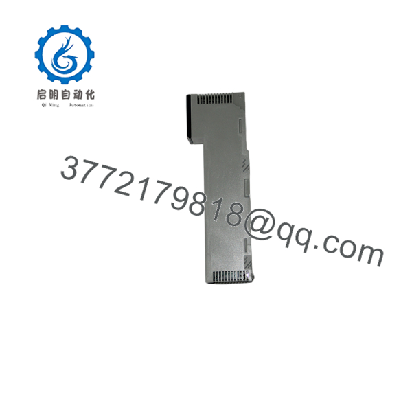
140DAI75300
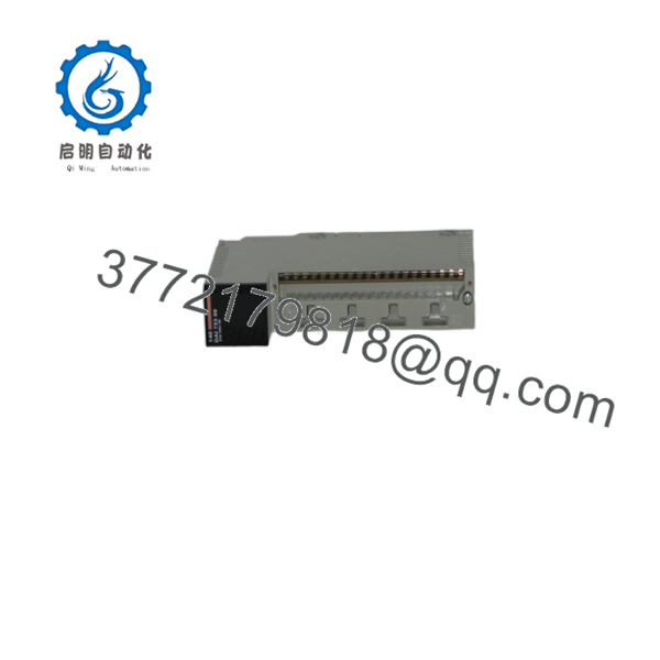
140DAI75300
Installation & Configuration Guide
Stage 1: Pre-Installation Preparation
⚠️ Safety First: Place the controlled process in a safe state and follow the plant’s electrical isolation and lockout/tagout procedures.
Before removing the existing module:
- Confirm the complete part number: 140DAI75300.
- Record the Quantum rack and slot position.
- Photograph the module label.
- Photograph the field terminal wiring.
- Identify all 32 input circuits.
- Record the associated field devices.
- Verify the field supply voltage.
- Back up the PLC project.
- Record the input states before shutdown where practical.
- Confirm that the replacement has the same electrical input characteristics.
Stage 2: Removing the Existing Module
- Place the controlled process in its approved safe condition.
- Isolate the relevant control power.
- Verify the absence of voltage.
- Label field conductors before disconnecting them.
- Photograph the terminal arrangement.
- Disconnect the field wiring.
- Release the module retaining mechanism.
- Remove the 140DAI75300 from the Quantum rack.
- Inspect the backplane connector.
- Inspect the terminal block and field wiring for heat damage or corrosion.
⚠️ Do not use the module’s physical position as the only identification method. Verify the part number on the module label.
Stage 3: Installing the Replacement
- Use appropriate ESD protection.
- Verify the replacement is 140DAI75300.
- Confirm the Quantum rack and slot.
- Insert the module into the backplane.
- Ensure the module is fully seated.
- Secure the module.
- Reconnect the field terminal assembly.
- Verify every conductor against the wiring documentation.
- Check the 24 VDC field supply.
- Inspect for loose or exposed conductors.
Installation Checklist:
- 140DAI75300 verified
- Correct Quantum rack
- Correct slot
- 24 VDC field supply verified
- All input wires identified
- Terminal block secure
- Module fully seated
- Input polarity checked
Stage 4: Commissioning & I/O Testing
- Perform a final wiring inspection.
- Restore control power.
- Check the module status indication.
- Connect to the PLC programming environment.
- Verify the module is recognized by the Quantum configuration.
- Monitor the input states.
- Activate representative field devices individually.
- Confirm the corresponding PLC input changes state.
- Test inputs across each channel group.
- Check for intermittent or stuck inputs.
- Confirm the PLC application receives the expected field states.
- Return the process to normal operation.
Input Troubleshooting
If an input does not change state, troubleshoot in this order:
Field device → field power → wiring → terminal block → module channel → PLC configuration
This sequence helps distinguish a failed 140DAI75300 from a field-side wiring or sensor problem.
Typical checks include:
- Measure the voltage directly at the input terminal.
- Compare the measured voltage with the module’s input threshold.
- Check the common/reference connection.
- Test the field device independently.
- Move a known-good signal to the suspect channel only if the plant’s test procedure permits it.
- Compare the PLC diagnostic state with the physical measurement.
Frequently Asked Questions
What is the 140DAI75300?
The 140DAI75300 is a Modicon Quantum discrete input module designed to interface 24 VDC digital field signals with a Quantum PLC.
How many inputs does the 140DAI75300 have?
It provides 32 discrete DC input channels, arranged in channel groups.
What type of field devices can be connected?
Typical applications include:
- Proximity switches
- Limit switches
- Pushbuttons
- Selector switches
- Relay contacts with suitable interface circuitry
- 24 VDC digital sensors
- Machine status contacts
Always verify the field device’s electrical characteristics before connecting it directly.
Is the 140DAI75300 an analog input module?
No. It is a discrete/digital input module. It is intended to detect defined ON/OFF states rather than continuously measure an analog process variable.
Can I replace the 140DAI75300 with another 32-point Quantum input module?
Do not select a replacement based only on channel count. Verify:
- Input voltage
- Input threshold
- Logic convention
- Channel grouping
- Isolation
- Terminal arrangement
- Quantum hardware configuration
- Application requirements
A 32-channel module with different electrical characteristics is not necessarily an acceptable substitute.
What should I check before ordering a 140DAI75300?
For an existing plant installation, provide the supplier with:
- Complete part number
- Hardware revision
- Quantity required
- Required condition
- Application/plant environment
- Required delivery date
- Whether terminal accessories are required
For a critical spare, request photographs of the actual module label before shipment.
What condition should I specify?
Use precise condition terminology:
- Factory Sealed — unopened original packaging
- New Original / New Surplus — unused original equipment
- Refurbished (tested) — previously used equipment that has been inspected and functionally tested
Avoid accepting an unspecified “used” or “tested” description when the module is required for a production-critical Quantum system. The supplied product-page framework calls for explicit condition disclosure and testing information.



