
 WhatsApp: +86 16626708626
 Email:
  Phone: +86 16626708626
Description
Key Technical Specifications
| Parameter | Specification |
|---|---|
| Manufacturer | Schneider Electric |
| Part Number | 140DDI35300 |
| Product Family | Modicon Quantum |
| Product Type | Low-voltage DC discrete input module |
| Number of Inputs | 32 |
| Input Groups | 4 groups × 8 channels |
| Input Voltage | 24 VDC |
| Input Voltage Limits | 19.2–30 VDC |
| Logic | Positive / sink |
| ON-State Voltage | 15–30 VDC |
| OFF-State Voltage | −3 to +5 VDC |
| Minimum ON-State Current | ≥2 mA |
| Maximum OFF-State Current | ≤0.5 mA |
| Input Impedance | 2.5 kΩ |
| Response Time | ≤1 ms ON→OFF / OFF→ON |
| Addressing | 2 input words |
| Bus Current | 330 mA |
| Power Dissipation | 1.7 W + 0.36 W × number of inputs ON |
| Group-to-Bus Isolation | 1,780 Vrms for 1 minute |
| Group-to-Group Isolation | 500 Vrms for 1 minute |
| Input Protection | Resistor-limited |
| Module Status | Active, fault, and individual input LEDs |
| Module Format | Standard |
| Approx. Weight | 0.3 kg |
| Operating Temperature | 0–60 °C |
| Storage Temperature | −40 to +85 °C |
| Relative Humidity | Up to 95%, non-condensing |
| Maximum Altitude | ≤5,000 m |
Schneider’s datasheet specifies 32 inputs, arranged in four groups of eight, with a 24 VDC nominal input and a 19.2–30 VDC operating range. The guaranteed ON state is 15–30 VDC and the guaranteed OFF state is −3 to +5 VDC.
Product Introduction
The Schneider Electric 140DDI35300 is a 32-point discrete input module for the Modicon Quantum automation platform. It receives 24 VDC field signals from devices such as proximity switches, limit switches, pushbuttons, relay contacts, and other binary sensors and transfers their states to the Quantum controller.
The module divides its 32 inputs into four groups of eight channels. It uses positive/sink input logic and requires no separate external power supply for the module itself; field devices provide the input signals. The published response time is 1 ms or less for both transitions.
The module also provides electrical isolation between the input groups and the Quantum bus, with 1,780 Vrms for one minute group-to-bus isolation and 500 Vrms for one minute group-to-group isolation.
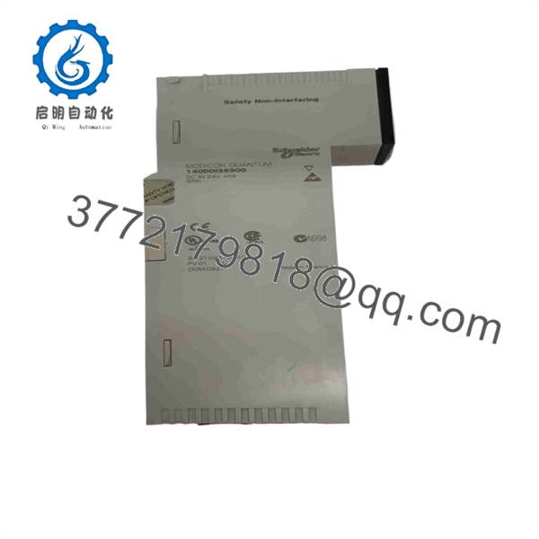
140DDI35300
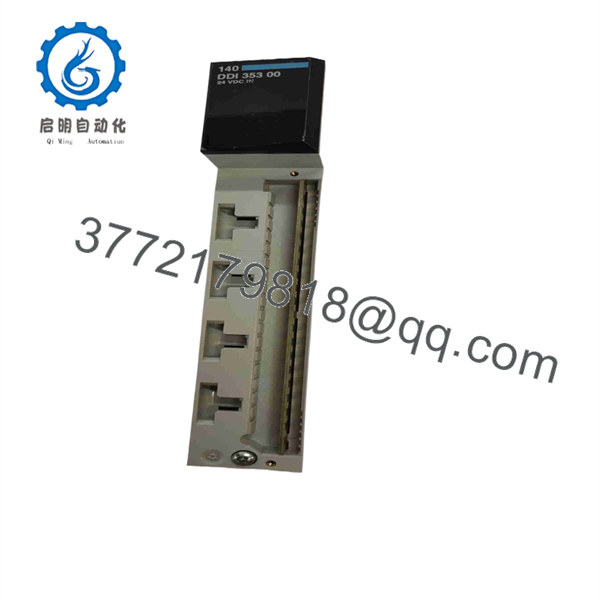
140DDI35300
Installation & Configuration Guide
Stage 1: Pre-Installation Preparation
⚠️ Safety First: Verify that the field circuits and Quantum rack are in a safe maintenance state before removing or wiring the module.
Before replacement:
- Record the complete part number: 140DDI35300.
- Photograph the existing wiring.
- Record the Quantum rack and slot number.
- Identify all four input groups.
- Label field wires before disconnecting them.
- Confirm the field devices use the expected 24 VDC signal.
- Save the PLC application and I/O configuration.
Stage 2: Remove the Existing Module
- Place the controlled process in its approved maintenance state.
- Isolate field power where required.
- Apply ESD protection.
- Photograph the module and terminal connections.
- Label each field circuit.
- Disconnect the field wiring.
- Release the module retention mechanism.
- Remove the module from the Quantum backplane.
- Inspect the backplane connector.
- Compare the removed module with the replacement.
Stage 3: Install 140DDI35300
- Verify the replacement part number.
- Confirm the Quantum rack and slot.
- Inspect the module connector.
- Insert the module into the correct slot.
- Seat it completely against the backplane.
- Secure the module.
- Reconnect field wiring according to the original channel assignment.
- Verify polarity.
- Check each of the four input groups.
- Confirm that no loose conductors remain.
Installation Checklist:
- 140DDI35300 verified
- Correct Quantum rack
- Correct slot
- 24 VDC field supply verified
- Input polarity verified
- Four input groups checked
- All terminals secured
- Module fully seated
Stage 4: Commissioning & Testing
- Restore field power.
- Restore the Quantum rack.
- Check the module’s Active indication.
- Check for an external-fault indication.
- Operate each field device individually.
- Verify the corresponding input LED.
- Monitor the input state in the PLC software.
- Confirm that each input maps to the correct PLC address.
- Test representative ON/OFF transitions.
- Verify the machine sequence.
- Check for intermittent or unstable inputs.
- Record the final test results.
⚠️ Troubleshooting Note: If an input remains OFF despite a field signal, measure the voltage directly at the module terminal. A reading outside the specified input thresholds can indicate field wiring, sensor, common/return, or power-supply problems rather than a failed Quantum module.
Frequently Asked Questions
What is the Schneider 140DDI35300?
The 140DDI35300 is a 32-channel, 24 VDC discrete input module for Modicon Quantum. It provides four groups of eight digital inputs.
What voltage does it accept?
The nominal input voltage is 24 VDC, with an operating range of 19.2–30 VDC. A signal between 15 and 30 VDC is guaranteed as an ON state, while −3 to +5 VDC is guaranteed as OFF.
How many inputs does it have?
It has 32 discrete inputs, organized as 4 groups × 8 channels.
What is the response time?
The specified response time is ≤1 ms for both state transitions.
Does the 140DDI35300 require an external power supply?
The module’s Quantum bus power is supplied through the rack. The published Quantum manual states that external power is not required for the module itself; the field circuits provide the input signals.
What is the bus current requirement?
The module requires approximately 330 mA from the Quantum bus.
Is 140DDI35300 discontinued?
Yes, but lifecycle status varies by Schneider region. Schneider USA lists it as discontinued on December 31, 2022, with end-of-service scheduled for December 31, 2030. Other Schneider regional pages show different commercial end dates.
What is the Schneider replacement?
Schneider identifies BMXDDI3202K, a Modicon X80 32-input, 24 VDC positive-logic module, as the recommended replacement. This should not be treated as a direct plug-in Quantum replacement; the rack/platform and I/O configuration must be evaluated as part of the migration.
Is 140DDI35310 the same module?
No. Schneider’s historical selection documentation indicates that the 140DDI35300 is the positive-logic version, while 140DDI35310 is the corresponding negative-logic variant. Do not substitute them without verifying the field wiring and application logic.
What should I specify when purchasing a replacement?
For a legacy 140DDI35300, specify the exact part number and condition: Factory Sealed, New Original/New Surplus, or Refurbished/Tested. For used or refurbished units, request clear photographs of the front label, terminal connector, and module LEDs before purchase.



