
 WhatsApp: +86 16626708626
 Email:
  Phone: +86 16626708626
Description
Key Technical Specifications
| Parameter | Value |
|---|---|
| Manufacturer | Schneider Electric / Modicon |
| Part Number | 140DDM39000 |
| Product Family | Modicon Quantum automation platform |
| Product Type | Mixed discrete I/O module |
| Total Discrete Points | 24 |
| Discrete Inputs | 16 inputs in 2 groups of 8 |
| Input Nominal Voltage | 24 V DC |
| Input Logic | Sink |
| Input ON State | 15–30 V DC; minimum 2 mA |
| Input OFF State | −3 to +5 V DC; maximum 0.5 mA |
| Input Impedance | 2,500 Ω |
| Discrete Outputs | 8 outputs in 2 groups of 4 |
| Output Type | Solid-state |
| Output Logic | Sink |
| Output Nominal Voltage | 24 V DC |
| Output Operating Range | 19.2–30 V DC typical |
| Maximum Output Current | 0.5 A per point; 2 A per group; 4 A per module |
| Output Voltage Drop | 0.4 V maximum at 0.5 A |
| Output Leakage Current | 0.4 mA maximum at 30 V DC |
| Output Response Time | Maximum 1 ms, ON-to-OFF and OFF-to-ON |
| Output Short-Circuit Protection | Transient voltage suppression; 5 A fuse per output group |
| Associated Output Fuse | 5 A per group |
| Maximum Inductive Load | 500 mH at 4 Hz |
| Maximum Capacitive Load | 50 µF |
| Output Transient Limit | 56 V DC for 1.3 ms |
| Input Addressing Requirement | 1 input word |
| Output Addressing Requirement | 0.5 output word |
| Group-to-Group Isolation | 500 Vrms for 1 minute |
| Group-to-Bus Isolation | 1,780 Vrms for 1 minute |
| Power Dissipation | 1.75+(0.36×input points ON)+(1.1×total output current)1.75 + (0.36 \times input points ON) + (1.1 \times total output current) W |
| Lifecycle Status | Discontinued December 31, 2022; scheduled end of service December 31, 2030 |
Schneider identifies the 140DDM39000 as a Modicon Quantum mixed discrete I/O module with 16 24 V DC inputs and eight solid-state outputs. Detailed product specifications identify sink logic on both inputs and outputs, with output capacity limited to 0.5 A per point, 2 A per group, and 4 A per module.
Product Introduction
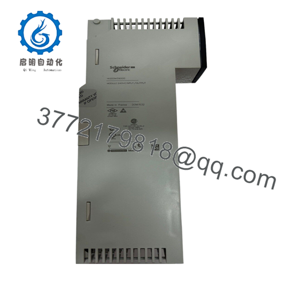
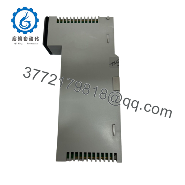
The Schneider Electric 140DDM39000 is a 24-point Modicon Quantum mixed discrete I/O module. It brings 16 sink-type 24 V DC status inputs and eight sink-type solid-state outputs into one Quantum rack slot for machine permissives, limit switches, relay coils, pilot lights, alarm devices, and low-current solenoid circuits.
This module is a direct spare for existing Quantum systems where both input and output density matter. It switches outputs in 1 ms or less and provides separate two-group output protection. Confirm the required field-device polarity before ordering: its outputs are sinking, so the load must be wired to a positive 24 V DC source and the module completes the return path.
140DDM39000
140DDM39000
Troubleshooting Quick Reference
| Symptom | Possible Cause | Relevance to This Part | Quick Check Method | Recommendation |
|---|---|---|---|---|
| All 16 inputs remain OFF | Missing 24 V DC field supply, common return open, incorrect sink-input wiring, loose terminal block, failed sensor supply, or failed module | ✅ Medium | Measure 24 V DC from the field device output to the correct input common using a Fluke 115 or equivalent meter. Confirm each input receives 15–30 V DC when the device is ON. Inspect the input common and terminal-block seating. | Check field power and input common wiring before replacing the module. |
| One input point does not turn ON | Failed sensor, broken wire, incorrect sensor polarity, loose terminal, damaged input channel, or PLC logic address error | ✅ Medium | Force the field device safely or apply a known 24 V DC test signal through an approved fused test lead. Verify 15–30 V DC at the input terminal and compare the module LED, raw input bit, and PLC tag. | Repair the sensor or wiring first. Replace the module only if a verified test signal fails on the same point. |
| Input LED is ON but PLC logic does not react | Incorrect I/O address, PLC logic interlock, input force, controller in STOP, stale HMI value, or program issue | ❌ Low | Check the raw input word in the Quantum controller. Confirm the module uses one input word and verify the configured slot/address. Check for forces and online logic conditions. | The module is likely healthy if its input LED and raw bit change together. Troubleshoot PLC logic or HMI mapping. |
| All eight outputs fail to energize | Missing external 24 V DC load supply, output-group fuses open, wrong sink-output wiring, PLC in STOP, output inhibit, or failed module | ✅ High | Confirm the external load supply is 19.2–30 V DC. Check both 5 A output-group fuses. Verify the PLC is commanding the correct half-word and inspect output-group common wiring. | Check external output power and fuses before replacing the module. The module does not create field voltage; it sinks the load return. |
| One output LED turns ON but the field load stays de-energized | Open load, blown field fuse, bad relay/solenoid coil, missing +24 V DC, wiring fault, or high-resistance terminal | ❌ Low to Medium | Measure voltage across the load while the output is commanded ON. Measure from the load’s positive terminal to the module output. Check coil resistance with power removed. | Troubleshoot the load and its supply first. If the LED is ON, the module is receiving the command. |
| One output will not turn ON but nearby points work | Failed output transistor, blown group fuse, overload, shorted load, wrong PLC address, wiring fault, or output force | ✅ Medium | Check the output’s raw command bit, LED status, external 24 V DC, group fuse, and load resistance. Disconnect the load under approved procedure and test with a known-good low-current load. | Do not fit a new module until the field load is checked for shorts. A shorted solenoid can damage a replacement output immediately. |
| Output group fuse opens repeatedly | Shorted cable, failed solenoid/relay coil, excessive inrush, incorrect load polarity, wiring to ground, or too much group current | ❌ Low to Medium | With power removed, measure resistance from each output circuit to common and inspect the field cable. Add all simultaneous load currents and confirm they remain below 2 A per group and 4 A total. | Correct the external short or overload. Do not install a larger fuse; use the specified 5 A group fuse only. |
| Output module overheats or has intermittent output dropouts | Continuous overload, poor cabinet cooling, inductive kickback, excessive group current, loose terminal, or internal damage | ✅ Medium to High | Measure actual load current on each active output. Confirm no output exceeds 0.5 A, no group exceeds 2 A, and total module load remains at or below 4 A. Inspect enclosure temperature and output wiring. | Reduce the load or add interposing relays. Use proper suppression across inductive loads and preserve current margin. |
| Output turns ON briefly, then shuts off | Short-circuit event, overloaded output, transient from inductive device, damaged coil, or failing output transistor | ✅ Medium | Monitor the output LED, PLC command bit, group fuse, and load voltage during the event. Inspect the coil for a flyback diode, RC snubber, or approved suppression device. | Correct the load transient or short. Do not bypass protection or repeatedly reset a blowing fuse. |
| New module fails after installation | Sink/source mismatch, incorrect terminal wiring, shorted external load, wrong output group fuse, damaged terminal block, or ESD damage | ✅ High | Photograph the old wiring before removal. Verify that loads connect to +24 V DC and the module sinks the return. Check all field circuits for shorts before energizing. | Correct wiring and load faults before installing another module. Sink-versus-source confusion is the classic commissioning mistake. |
❗ Sink-output warning: This module has sinking outputs. It does not source +24 V DC to a load. Wire the load to the positive side of the field supply, then route the return through the assigned module output. Wiring a sink output as a source output produces a dead load or a short circuit.
❗ Current-limit warning: Keep each output at or below 0.5 A, each four-point group at or below 2 A, and the entire module at or below 4 A. A group fuse may survive an overload long enough to heat the output stage, so do not design at the limit.
❗ Inductive-load warning: Use appropriate suppression for relay coils, solenoids, valves, and contactors. I have seen an output card blamed for “random failures” when the actual problem was a coil without suppression throwing repeated transients into the field circuit.
❗ Fuse warning: Use the specified 5 A fuse per output group. Never install an oversized fuse to stop nuisance blowing. Find the shorted cable, failed coil, or excess load current instead.
If you are stuck, send technical support the Quantum rack/CPU model, module slot, front LED status, raw I/O words, photos of the terminal block, input and output voltage readings, output-group fuse condition, connected load list, and complete 140DDM39000 label. Keep these checks in mind and you will save yourself 90% of typical rework time.
Frequently Asked Questions (FAQ)
What does the Schneider 140DDM39000 do?
The 140DDM39000 is a Modicon Quantum mixed discrete I/O module. It combines 16 sink-type 24 V DC inputs and eight sink-type 24 V DC solid-state outputs in a single standard Quantum module.
Are the outputs sourcing or sinking?
They are sinking outputs. The load must receive positive voltage from the external 24 V DC field supply, while the 140DDM39000 output provides the switched return path. Verify the polarity of every relay coil, solenoid, lamp, and interface circuit before wiring.
How much current can each output handle?
Each output can switch up to 0.5 A. The module limits each four-output group to 2 A and the combined module load to 4 A. Do not calculate only average current; account for simultaneous loads and inrush current from relays, valves, and lamps.
Can I connect a solenoid valve directly to an output?
Yes, if the valve is a 24 V DC load within the 0.5 A point rating, group-current limit, total-module limit, and inductive-load specification. Add an appropriate suppression device based on the valve and plant design. For larger coils, high inrush loads, or frequent cycling, use an interposing relay or properly rated interface module.
Is the 140DDM39000 interchangeable with a source-output module?
No. A source-output module supplies positive voltage, while the 140DDM39000 completes the negative return path. The terminal wiring, field-device polarity, troubleshooting method, and fault behavior differ. Replacing a source-output design with a sink-output module without rewiring can cause failed outputs or damage equipment.
Can I hot-swap the 140DDM39000?
Do not assume it can be hot-swapped. Removing the module during operation can drop outputs, change input states, create process trips, or generate unsafe motion. Put the equipment in a safe state, isolate field energy where necessary, document wiring, and follow your approved Quantum maintenance procedure before removal.
Is the 140DDM39000 obsolete?
Yes. Schneider Electric lists the 140DDM39000 as discontinued on December 31, 2022, with end of service scheduled for December 31, 2030. For production-critical Quantum racks, maintain tested spare inventory and plan an orderly migration before a forced failure dictates the schedule.
Why is a New Surplus 140DDM39000 cheaper than factory stock?
New Surplus stock usually comes from unused project inventory, storeroom spares, system upgrades, distributor liquidation, or integrator stock. It can be original Schneider equipment, but it is outside active factory distribution and may have older packaging or limited traceability.
A credible supplier should verify the complete label and housing condition, inspect terminal-block and backplane contacts, check for corrosion or heat damage, power the module in a genuine Quantum rack, test all 16 inputs with 24 V DC signals, and test all eight outputs under controlled loads. Test the output LED response, group protection, and 24 V DC switching behavior. Request actual unit photos, a dated test report, warranty terms, stock confirmation, and an ESD-safe packing statement before placing the order.



