
 WhatsApp: +86 16626708626
 Email:
  Phone: +86 16626708626
Description
Key Technical Specifications
| Parameter | Value |
|---|---|
| Manufacturer | Schneider Electric / Modicon |
| Part Number | 140DRA84000 |
| Product Family | Modicon Quantum automation platform |
| Product Type | Relay discrete output module |
| Discrete Output Count | 16 |
| Contact Type | 1 normally open contact per output |
| Contact Form | Form A |
| Output Voltage, AC | 20–250 V AC |
| Output Voltage, DC Low Range | 5–30 V DC |
| Output Voltage, DC High Range | 30–150 V DC |
| Addressing Requirement | 1 output word |
| Minimum Load | 50 mA at 5–30 V DC or 20–250 V AC |
| Maximum Resistive Load | 2 A at 250 V AC or 30 V DC, at 60 °C |
| Maximum DC Load, 30–150 V DC | 300 mA resistive |
| Maximum Tungsten Load | 1 A at 250 V AC or 30 V DC |
| Maximum Motor Load | 1 A at 250 V AC or 30 V DC, 1/8 hp, cos φ = 0.4 |
| Switching Capacity | 500 VA resistive |
| Maximum Surge Current | 10 A for 10 ms, capacitive load |
| Response Time, OFF to ON | Maximum 10 ms |
| Response Time, ON to OFF | Maximum 20 ms |
| Output Overvoltage Protection | Internal 275 V varistor |
| Electrical Life, 250 V AC Resistive | 200,000 operations at 2 A |
| Mechanical Life | 10,000,000 operations |
| Channel-to-Channel Isolation | 1,780 Vrms AC for 1 minute |
| Channel-to-Bus Isolation | 2,500 V DC or 1,780 Vrms AC for 1 minute |
| Bus Current Requirement | 1,100 mA maximum |
| Power Dissipation | 5.5+(0.5×number of active outputs)5.5 + (0.5 \times number of active outputs) W |
| Local Indicators | 16 green output-status LEDs; 1 green Active LED; 1 red external-fault LED |
| Operating Temperature | 0 to 60 °C |
| Storage Temperature | −40 to +85 °C |
| Lifecycle Status | Discontinued December 31, 2022; end of service December 31, 2030 |
The Schneider Electric 140DRA84000 is a Modicon Quantum 16-point normally open relay output module. It switches 20–250 V AC, 5–30 V DC, or 30–150 V DC loads and is rated for 2 A resistive switching at 250 V AC or 30 V DC, with derating for higher-voltage DC applications.
Product Introduction
The Schneider Electric 140DRA84000 is a 16-point relay output module for Modicon Quantum PLC racks. Each point provides a normally open Form A contact for switching external AC or DC loads such as interposing relays, contactors, lamps, alarms, small motors, and solenoid interfaces.
This module is used where dry-contact switching and mixed-voltage load compatibility are more important than high-speed transistor outputs. It supports 20–250 V AC and up to 150 V DC, but high-voltage DC switching requires strict load derating. Verify the load type, voltage, current, inrush, and switching frequency before selecting or replacing the module.
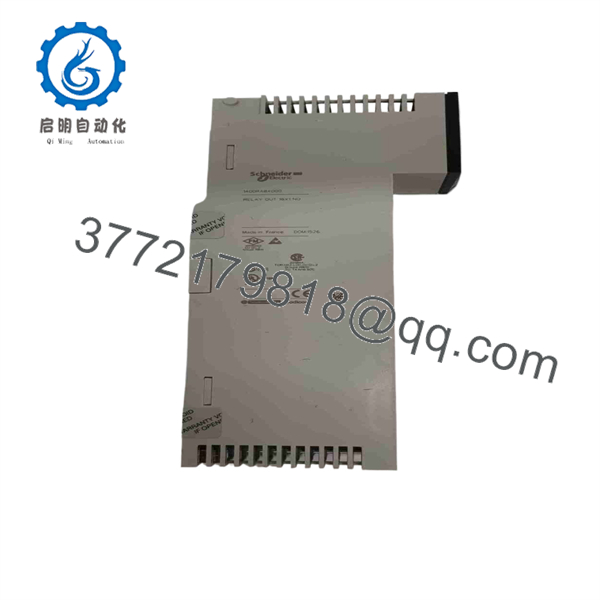
140DRA84000
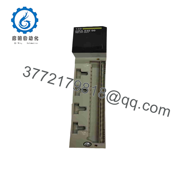
140DRA84000
Troubleshooting Quick Reference
| Symptom | Possible Cause | Relevance to This Part | Quick Check Method | Recommendation |
|---|---|---|---|---|
| All 16 loads remain OFF | PLC in STOP, module not seated, backplane communication fault, incorrect output addressing, missing field supply, common wiring issue, or module fault | ✅ Medium to High | Check the green Active LED and Quantum CPU RUN status. Verify the PLC output word online. Measure field voltage at the load supply and confirm common wiring at the terminal block. Power down before reseating the module. | Check PLC state, field power, terminal wiring, and backplane seating before replacing the module. |
| One output LED is ON but the load remains de-energized | Open field fuse, missing load supply, broken wire, failed coil/lamp, poor terminal connection, welded/open relay contact, or wrong wiring | ✅ Medium | Measure voltage across the load while the output is commanded ON. Then measure from source to the module output and from module output to return. With power removed, measure load continuity. | Troubleshoot the load circuit first. An ON LED confirms the PLC has commanded the output; it does not prove current reaches the load. |
| One output will not energize but adjacent outputs work | Failed relay contact, incorrect PLC bit, loose terminal, broken field wire, failed load, or output channel fault | ✅ Medium | Force the output only under approved maintenance conditions. Verify the raw PLC output bit and green LED. Check continuity across the relay contact with power removed and the output commanded by a safe test method. | Test with a known-good low-current load. Replace the module only after wiring and the external device are excluded. |
| Output contact is welded closed | Excessive inrush, capacitive load, inductive kickback, load current above rating, short circuit, or relay contact wear | ✅ High | Remove field power immediately if the output controls hazardous equipment. With power removed, verify contact continuity when the output is OFF. Inspect the connected load and suppression device. | Replace the module and correct the load circuit. Add appropriate interposing relays, RC snubbers, MOVs, or other approved suppression. |
| Output turns ON briefly then drops out | PLC logic interlock, controller fault, field supply collapse, overloaded load, output contact issue, or external safety circuit opening | ❌ Low to Medium | Trend the PLC output bit, module LED, and field voltage at the same time. If the PLC bit and LED remain ON while the load drops, check contact condition and field wiring. | Separate logic behavior from relay-contact behavior before replacing hardware. |
| Red external-fault LED is ON | Field-side wiring problem, overloaded output, external supply fault, terminal issue, or module fault | ✅ Medium | Identify active output points and inspect their loads. Check fuses, wiring insulation, field supply voltage, and output current. Review PLC diagnostics if available. | Correct the external issue first. The red fault LED is a diagnostic starting point, not proof of a failed card. |
| Module overheats or fails after adding loads | Total load too high, high inrush current, excessive switching rate, poor ventilation, relay arcing, or incorrect DC load rating | ✅ High | Measure load current per point and identify load type. Confirm resistive loads do not exceed 2 A at 250 V AC/30 V DC, and that 30–150 V DC loads stay at or below 300 mA. Check cabinet ambient temperature. | Derate the circuit, use interposing relays/contactors, and avoid operating near limits. High-voltage DC is harder on relay contacts than AC. |
| 24 V DC load works, but 120/230 V AC load does not | Incorrect line-voltage wiring, open neutral, load-side fuse issue, incorrect terminal assignment, or failed field device | ❌ Low to Medium | With qualified personnel and appropriate PPE, measure line voltage at the source, relay terminal, and load. Confirm the circuit uses the correct normally open contact path. | Check field wiring and protective devices first. Do not test line-voltage circuits without proper arc-flash and electrical-safety procedures. |
| New module fails immediately after installation | Incorrect terminal wiring, line voltage applied to wrong point, shorted load, high inrush, damaged terminal block, or ESD damage | ✅ High | Compare the old and new terminal wiring against the wiring diagram. Inspect each load for shorts and verify source voltage before energizing. Confirm that normally closed terminals are not used; the module provides normally open contacts only. | Correct wiring and external faults before installing another module. Never rely on wire colors or memory. |
| Relay clicks but PLC/HMI status does not update | PLC output mapping, HMI tag issue, program logic, forcing condition, or communication delay | ❌ Low | Check the raw output word and module LED. Listen for the relay click only as a secondary indicator. Verify the HMI tag points to the correct PLC address. | If the output LED and relay action match the PLC bit, troubleshoot logic or HMI mapping. |
❗ Relay-contact warning: These are normally open Form A contacts. There is no normally closed field contact available from this module. Do not land a critical circuit on an assumed NC terminal; documentation identifies NC as not connected.
❗ DC derating warning: At 30–150 V DC, the maximum resistive load is only 300 mA per point. Relay contacts extinguish AC arcs more easily than DC arcs. A circuit that is acceptable at 230 V AC can destroy a relay contact at far lower DC current.
❗ Minimum-load warning: The module specifies at least 50 mA at 5–30 V DC or 20–250 V AC. Do not use its mechanical relay contacts for dry, ultra-low-level instrument switching without validating contact-wetting requirements.
❗ Inductive-load warning: A relay coil, contactor, solenoid, or small motor produces a switching transient. Use appropriately selected suppression at the load. I have seen output contacts weld because a coil circuit lacked a basic snubber or suppression device.
If you are stuck, send technical support the Quantum CPU model, module slot number, green and red LED status, PLC output word, wiring photos, field voltage measurements, load current, load type, fuse status, and the full 140DRA84000 label. Keep these checks in mind and you will save yourself 90% of typical rework time.
Frequently Asked Questions (FAQ)
What does the Schneider 140DRA84000 do?
The 140DRA84000 is a Modicon Quantum 16-point relay discrete output module. It provides 16 normally open Form A contacts for switching AC and DC field loads from a Quantum PLC output word.
Are the 16 outputs normally open or normally closed?
All 16 outputs are normally open. Each channel has one Form A contact. The published wiring diagram identifies the normally closed terminal as not connected, so do not use this module where a true normally closed output contact is required.
What voltages and currents can each output switch?
Each output can switch 20–250 V AC, 5–30 V DC, or 30–150 V DC. For resistive loads at 250 V AC or 30 V DC, the maximum is 2 A per point at 60 °C. For 30–150 V DC, the maximum resistive load is 300 mA per point. The module’s resistive switching capacity is 500 VA.
Can I drive a contactor or solenoid directly?
You can drive a coil directly only if its steady-state and inrush current remain inside the module’s ratings and proper suppression is installed. For larger contactors, high-inrush valves, frequent cycling, or safety-critical loads, use an interposing relay or a properly rated contactor interface. That protects the Quantum relay contacts and makes future field repair easier.
Can I use the 140DRA84000 for low-level dry-contact signals?
Usually, no. The published minimum load is 50 mA for the listed AC and low-voltage DC ranges. For low-level signals, instrumentation contacts, or circuits that cannot supply contact-wetting current, use an interface designed for dry-contact or low-level switching.
Can I hot-swap the 140DRA84000?
Do not assume hot swapping is safe. Removing the module can drop 16 field outputs, and those outputs may control contactors, valves, alarms, or process equipment. Put the process in a safe state, isolate field voltage where required, document wiring, and follow the approved Quantum maintenance procedure before replacement.
Is the 140DRA84000 obsolete?
Yes. Schneider Electric lists the 140DRA84000 as discontinued on December 31, 2022, with end of service on December 31, 2030. Plants using Quantum relay I/O should keep verified spares and plan a controlled platform migration before a failure forces an emergency redesign.
Why is New Surplus 140DRA84000 stock cheaper than factory supply?
New Surplus stock generally comes from unused project inventory, plant storerooms, system upgrades, integrator spares, or distributor liquidation. It may be genuine Schneider hardware, but it is outside the active factory channel. For relay modules, long storage also makes contact condition and packaging history worth checking.
A credible supplier should inspect labels, terminal points, housing, backplane contacts, and relay-contact condition; test the module in a genuine Quantum rack; command all 16 outputs; verify LED response; and switch controlled AC/DC test loads within rating. The supplier should document results, inspect for contact sticking or abnormal heating, and package the module in an ESD shielding bag with protective cushioning.
Request actual unit photographs, a dated test report, warranty terms, confirmed stock quantity, shipping lead time, and the exact condition designation—New Original, New Surplus, or Refurbished (tested)—before issuing a purchase order.



