
 WhatsApp: +86 16626708626
 Email:
  Phone: +86 16626708626
Description
Key Technical Specifications
| Parameter | Value |
|---|---|
| Manufacturer | Schneider Electric / Modicon |
| Model | AS-B875-111 |
| Product Family | Modicon 800 Series / 984 I/O |
| Product Type | Analog Input Module |
| Channel Configuration | 8 differential or 16 single-ended, user selectable |
| Resolution | 14 bit |
| Current Input Ranges | ±20 mA, 0–20 mA, 4–20 mA |
| Voltage Input Ranges | ±5 VDC, 0–5 VDC, 1–5 VDC, ±10 VDC, 0–10 VDC |
| Accuracy | ±0.1% |
| Linearity | ±0.05% |
| Update Time | 10 ms for 8 inputs; 20 ms for 16 inputs |
| Voltage-Mode Impedance | >10 MΩ |
| Current-Mode Impedance | 250 Ω |
| Channel-to-Channel Isolation | 30 VAC |
| Channel-to-Module Isolation | 1,500 VAC for 1 minute |
| Power Requirement | +5 V at 500 mA; +4.3 V at 900 mA; −5 V at 0 mA |
| Rack Space | 1 slot |
| Weight | Approximately 3.52 lb (1.6 kg) |
| Terminal Connector | AS-8535-000 |
These specifications are consistent across available Modicon 800/984 technical documentation.
Product Introduction
The Schneider Electric Modicon AS-B875-111 is a legacy analog input module for Modicon 800 Series and 984-class PLC I/O systems. It converts voltage and current process signals into digital values and can be configured for either 8 differential or 16 single-ended inputs.
Its main technical distinction is the combination of 14-bit resolution, multiple bipolar and unipolar input ranges, and selectable channel configuration. This makes it useful when maintaining an existing 984/800-series installation where the original I/O architecture must be retained. Schneider documentation also identifies the AS-B875-111 in legacy B800-to-X80 migration documentation, so verify the migration wiring carefully before substituting a modern module.
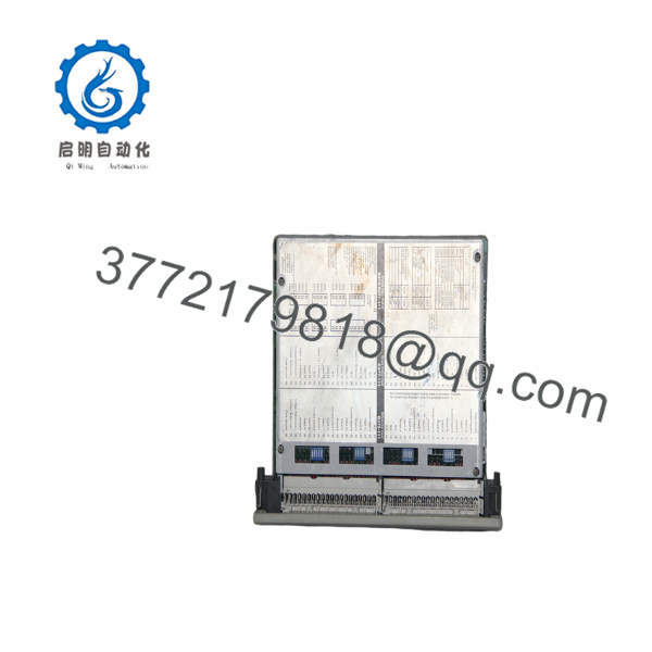
AS-B875-111
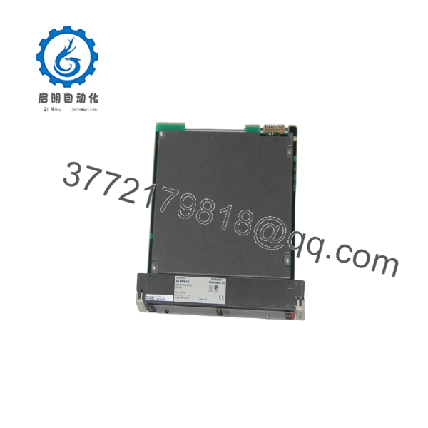
AS-B875-111
Installation & Configuration Guide
Stage 1: Pre-Installation Preparation — Approximately 5–10 Minutes
⚠️ Safety First: Notify operations, place the controlled process in a safe state, and follow the site’s lockout/tagout procedure before removing the module. Do not assume this legacy I/O module is hot-swappable.
Tools Required:
- ESD wrist strap
- Appropriate screwdriver
- Digital multimeter
- Wire labels
- Smartphone or camera for configuration photographs
Data Backup:
- Confirm the exact replacement number: AS-B875-111.
- Record the PLC rack and slot position.
- Photograph the existing terminal wiring before disconnecting anything.
- Record the existing channel configuration.
- Save the current PLC application and configuration where applicable.
- Record any diagnostic indications before shutdown.
Stage 2: Removing the Old Module — Approximately 5 Minutes
- Remove the module cover or front access components as applicable.
- Label every field wire before disconnecting it.
- Disconnect the terminal connector without pulling on individual conductors.
- Release the module’s mechanical retaining mechanism.
- Pull the module straight out of the rack.
- Inspect the mating connector and rack area for contamination, bent contacts, or physical damage.
⚠️ Keep the removed AS-B875-111 beside the replacement until commissioning is complete. The terminal arrangement and channel configuration are useful references during troubleshooting.
Stage 3: Installing the Replacement — Approximately 5–10 Minutes
- Put on the grounded ESD wrist strap before handling the replacement board.
- Confirm that the replacement marking reads AS-B875-111.
- Verify that the terminal connector and mechanical keying correspond to the existing installation.
- Install the module into the correct rack slot.
- Seat the module fully without forcing it.
- Reconnect the terminal connector.
- Verify every wire against the photographs and wiring documentation before applying power.
The AS- supports both 8 differential and 16 single-ended configurations. The distinction matters during wiring because the terminal assignment changes with the selected configuration.
Self-Check:
- Correct AS- model
- Correct rack slot
- Terminal connector fully seated
- Wiring verified
- Channel configuration verified
- ESD precautions maintained
Stage 4: Power-On & Testing — Approximately 10 Minutes
- Check the supply rails with a multimeter before powering the rack.
- Power the rack according to the site’s approved startup procedure.
- Observe the module status indication.
- Check the PLC’s I/O diagnostic information.
- Verify that each configured analog channel reports a plausible value.
- Apply a known test signal where practical.
- Compare the PLC value against the calibrated input source.
- Return field devices to normal operation only after the I/O checks pass.
Schneider Electric specifically documents the AS- ACTIVE LED behavior: a rapid flash indicates initialization, while a slow flash indicates that at least one input is out of range.
Troubleshooting Note: If the ACTIVE LED continues flashing slowly after startup, check the field signal range and channel configuration before assuming the replacement module is defective.
Frequently Asked Questions (FAQ)
Can the AS- be hot-swapped?
Do not treat it as a hot-swappable module unless the specific rack architecture and OEM documentation explicitly permit live removal. For a legacy Modicon 800/984 installation, the safer replacement procedure is to place the process in a safe state and remove power according to the site’s LOTO procedure.
What type of signals does the AS- accept?
It accepts multiple voltage and current ranges, including 4–20 mA, 0–20 mA, ±20 mA, 1–5 VDC, 0–5 VDC, ±5 VDC, 0–10 VDC, and ±10 VDC.
Is the AS- an 8-channel or 16-channel module?
It supports 8 differential inputs or 16 single-ended inputs, with the configuration being user selectable. Do not assume that a replacement module can simply be wired according to an 8-channel diagram without checking the existing configuration.
What resolution does this module provide?
The AS- provides 14-bit analog-to-digital resolution. Published specifications also list ±0.1% accuracy and ±0.05% linearity.
Is the AS- obsolete?
It is a legacy Modicon product, and current third-party lifecycle listings identify it as discontinued. That does not mean it cannot be sourced, but available units may come from surplus, used, or refurbished inventory.
Can I replace it with a modern Schneider Electric analog input module?
Potentially, but do not treat it as a drop-in substitution. Schneider documentation includes an AS–to-Modicon X80 migration path, but the wiring map and receiving module configuration must be checked carefully.
Will I receive a genuinely new AS-?
That depends on the seller’s actual inventory. Legacy modules are available in different conditions, including factory-sealed, new surplus, used, and refurbished. The exact condition, revision, accessories, and test status should be confirmed before purchase rather than inferred from the product number alone.



