
 WhatsApp: +86 16626708626
 Email:
  Phone: +86 16626708626
Description
Key Technical Specifications
- Analog Input Channels: 8
- Input Type: Differential
- Signal Ranges: 1–5 V; 4–20 mA
- Resolution: 12 bits
- Input Impedance: Greater than 20 MΩ voltage; 250 Ω current, ±0.01%
- Absolute Maximum Input: 50 V DC voltage; 25 mA current
- Absolute Accuracy: ±0.05% of full scale; ±0.1% of full scale maximum
- Linearity Error: ±0.04%
- Update Time: 5 ms
- Filter: Single-pole low-pass; −3 dB at 15 Hz ±20%
- Isolation: 1,000 V DC channel-to-bus; 3,000 V DC for 60 seconds
- Channel-to-Channel Isolation: 30 V DC
- Common-Mode Rejection: Greater than −72 dB at 60 Hz
- Bus Current Requirement: 240 mA
- Power Dissipation: 2 W
- Fault Detection: Broken wire on 4–20 mA; undervoltage on 1–5 V
- Addressing Requirement: 9 input words
Specifications are based on Schneider Electric product documentation and the associated technical datasheet. Confirm the exact hardware revision and terminal arrangement before installation.
Product Introduction
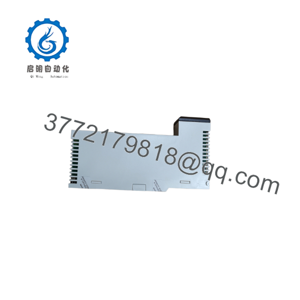
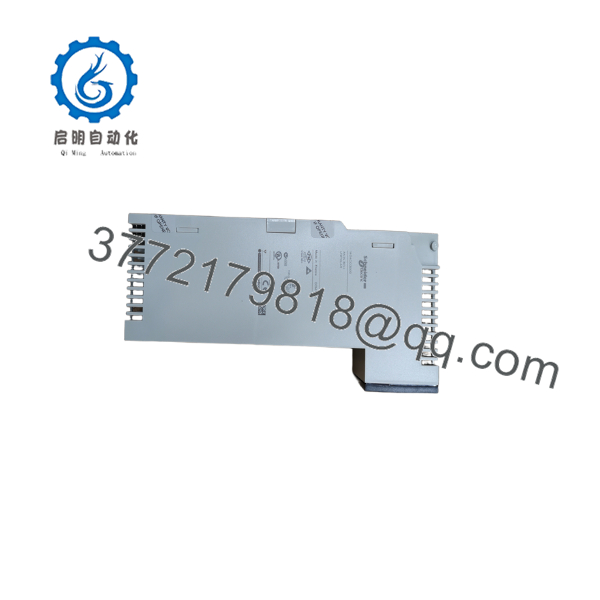
The Schneider Electric 140ACI03000 is an 8-channel differential analog input module for the Modicon Quantum PLC platform. It accepts 1–5 V and 4–20 mA process signals, digitizes them at 12-bit resolution, and updates input data every 5 ms for instrumentation and process-control applications.
Its 250 Ω current input impedance, high voltage input impedance, channel-to-bus isolation, and broken-wire detection suit standard industrial transmitters. Use the documented Quantum rack configuration and verify firmware, addressing, wiring, and module revision before treating it as a direct replacement.
Troubleshooting Quick Reference
| Symptom | Possible Cause | Relevance to This Part | Quick Check Method | Recommendation |
|---|---|---|---|---|
| No module or bus LED indication | Rack power, backplane, or seating fault | ❌ Low to medium | Measure the Quantum rack supply and verify the module is fully seated; inspect adjacent module LEDs | Check rack power, fuses, and backplane before replacing the 140ACI03000 |
| Input values remain at zero | Missing transmitter power, open loop, or incorrect wiring | ✅ Medium | Measure loop current directly at the channel terminals; confirm approximately 4–20 mA under operating conditions | Verify field power, polarity, common wiring, and terminal assignments |
| Input value is unstable | Electrical noise, poor shielding, or grounding issue | ✅ Medium | Compare the field signal with a calibrated multimeter at the module terminals; inspect shield termination | Correct shielding and grounding, then check the module filter and signal source |
| Channel fault LED is active | Broken wire, out-of-range signal, or input fault | ✅ High | Check loop continuity and measure current; inspect the PLC diagnostic buffer for the affected channel | Correct the field circuit first; replace the module only if the fault follows the channel |
| 4–20 mA signal reads incorrectly | Wrong range configuration or scaling error | ✅ Medium | Confirm the configured range, raw input word, and engineering-unit scaling in the Quantum application | Correct configuration and scaling before changing hardware |
| 1–5 V input shows undervoltage | Signal below 1 V, open circuit, or incorrect reference wiring | ✅ High | Measure voltage between the specified differential input terminals with a calibrated meter | Repair the signal source or wiring; replace the module only after confirming the input circuit |
| All channels fail together | Rack power, bus communication, or configuration issue | ❌ Low | Check module recognition, rack supply, bus status, and application diagnostics | Investigate the rack and CPU before replacing this module |
| Only one channel fails | Damaged input channel, terminal fault, or field wiring issue | ✅ High | Move a known-good signal to the suspect channel only when the wiring and process permit it | If the fault remains on the same channel, replacement is reasonable |
| Values are offset but repeatable | Transmitter calibration or scaling mismatch | ❌ Low to medium | Compare the module reading with the measured terminal signal and a known reference source | Calibrate the transmitter or correct PLC scaling |
| Communication timeout after replacement | Firmware, rack configuration, or module identification mismatch | ✅ Medium | Compare the removed module’s label, hardware revision, and diagnostic response with the replacement | Confirm Quantum compatibility and firmware requirements before extended troubleshooting |
Do not replace the module solely because the PLC reports bad analog data. Check the 5 V rack supply, field-loop power, terminal wiring, scaling, shielding, and diagnostic buffer first. If the fault remains, contact technical support with clear photos of the label and terminal wiring, the module LED status, hardware revision, and the PLC diagnostic logs.

- 140ACI03000
- 140ACI03000
Frequently Asked Questions (FAQ)
What is the Schneider Electric 140ACI03000?
It is an 8-channel differential analog input module for the Modicon Quantum automation platform. The module accepts 1–5 V and 4–20 mA signals and provides 12-bit digital input data to the PLC.
Is the 140ACI03000 a 16-channel current input module?
No. Schneider Electric documentation identifies the 140ACI03000 as an 8-channel multirange analog input module. Listings that describe it as a 16-channel, 14-bit current-only module should be checked carefully because they may confuse it with another Quantum part number.
Can I use it as a direct replacement?
Only after confirming the existing module’s full part number, hardware revision, rack configuration, signal range, addressing, and terminal wiring. Do not assume that a similar-looking Quantum analog module has the same pinout or configuration requirements.
Does replacing the module retain the PLC program?
The PLC application normally remains stored in the CPU or control-system memory, not in the analog input module itself. However, record the old module’s configuration, rack position, channel ranges, scaling, and any DIP-switch or jumper settings before removal. Download or back up the PLC project before making the change.
Can I hot-swap the 140ACI03000?
Do not assume hot swapping is permitted. Follow the Quantum hardware manual and the site’s change-control procedure. Unless the rack, power supply, and system configuration are specifically approved for live replacement, isolate power before removing the module.
Why is this module cheaper than a factory-supplied replacement?
Lower pricing may reflect surplus inventory, discontinued-stock sourcing, opened packaging, or a warranty period different from Schneider Electric’s original distribution channel. The seller should state whether the unit is Factory Sealed, New Original/New Surplus, or Refurbished and Tested. Ask for the serial-label photo, stock condition, test report, warranty duration, and return terms before purchase.
What should I verify before ordering?
Confirm the exact model number 140ACI03000, the required 1–5 V or 4–20 mA signal range, channel count, Quantum rack compatibility, terminal block arrangement, and required delivery condition. Also request current photos and confirmation that the supplied unit matches your installed hardware revision.



