WhatsApp: +86 16626708626
 Email:
 Phone: +86 16626708626
Description
Key Technical Specifications
| Parameter | Specification |
|---|---|
| Manufacturer | SCHROFF / nVent |
| Model | MPS022 |
| Part number | 13100203 / 13100-203 |
| Power supply type | AC/DC switch-mode power supply |
| System format | 6U VMEbus rack module |
| Rated output power | 224 W, as listed by a supplier |
| AC input voltage | 90–264 V AC, per available product listing |
| AC input frequency | 47–63 Hz, per available product listing |
| DC input range | 130–350 V DC, per available product listing |
| Main output | +5 V DC, 25 A |
| Auxiliary output | +12 V DC, 6 A |
| Auxiliary output | −12 V DC, 2 A |
| Backplane interface | H15 connector, as described by supplier documentation |
| Rack signals | Power OK and AC-fail signaling are listed for the module family |
| Installation | Compatible VME rack power-supply slot |
| Operating temperature | Verify the applicable manufacturer’s derating curve |
| Current availability | Confirm with the seller |
The part number and power-supply identity are supported by industrial parts and repair listings. Detailed electrical values above are reported in available product listings and should be checked against the unit’s nameplate and the applicable SCHROFF technical documentation before use.
Product Introduction
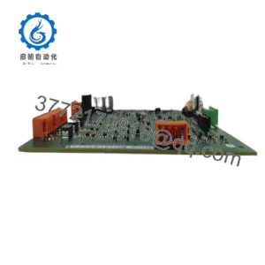
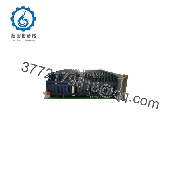
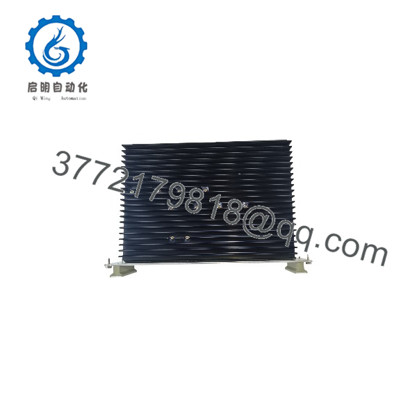
The SCHROFF MPS022 13100203 is a modular power supply intended for compatible VMEbus industrial computer systems. It provides multiple DC output rails for processor cards, interface modules, and other rack-mounted electronics. Its replacement value depends on maintaining the original system’s voltage requirements, connector layout, and rack integration. For legacy control equipment, matching the exact power-supply part number is important because a unit with a similar form factor may have different output ratings or backplane signaling.
Installation and Configuration Guide
Stage 1: Verify Compatibility
- Confirm the installed unit is marked MPS022 and 13100203 or 13100-203.
- Check the required +5 V, +12 V, and −12 V loads against the power supply’s rated outputs.
- Verify the rack format, mechanical dimensions, connector type, and backplane pin assignments.
- Check whether the rack uses redundant power supplies or power-fail monitoring.
- Obtain the correct installation documentation for the specific hardware revision.
Stage 2: Prepare for Removal
- Follow the equipment manufacturer’s shutdown procedure.
- Isolate the input power and verify that the supply is de-energized before handling it.
- If the rack has redundant supplies, follow the rack documentation before removing a module; do not assume that this specific configuration supports live removal.
- Label the existing module position and any associated power or monitoring connections.
Stage 3: Install the Replacement
- Inspect the replacement unit for damaged connectors, bent pins, corrosion, or other visible defects.
- Align the module with the intended rack guides and connector.
- Insert it using the manufacturer’s specified procedure; do not force it into the slot.
- Verify that the module is seated securely and that any retention hardware is engaged.
- Confirm that the backplane and connected loads are compatible with the replacement’s output configuration.
Stage 4: Power-Up and Testing
- Restore input power according to the approved commissioning procedure.
- Check the power-supply status indicators, if fitted.
- Measure the DC rails using the approved test points and procedure.
- Confirm that the output voltages remain within the limits specified in the manufacturer’s documentation under the intended load.
- Check the rack’s power-good and power-fail monitoring functions where applicable.
- Verify normal startup of the installed processor and I/O cards before returning the system to service.
Stage 5: Safety and Troubleshooting
- Do not exceed the rated output current or total power limit.
- Do not change backplane wiring or connector pin assignments based only on a similar-looking replacement.
- If a DC rail is missing or unstable, check the input supply, connected load, connectors, and rack requirements before diagnosing the power supply itself.
- If the module overheats or repeatedly shuts down, investigate ventilation, load current, and the manufacturer’s derating requirements.
- Use qualified personnel for electrical testing and maintenance of industrial rack power systems.
MPS022 13100203
MPS022 13100203
Frequently Asked Questions
Q1: What is the SCHROFF MPS022 13100203 used for?
It is an industrial power supply used in compatible rack-based automation and computing systems. It provides multiple DC rails for electronic modules installed in the rack.
Q2: What are its output voltages?
Available listings identify +5 V DC, +12 V DC, and −12 V DC outputs. Confirm the actual ratings and output configuration against the unit label before connecting loads.
Q3: Are 13100203 and 13100-203 the same part?
Supplier listings use both number formats for the SCHROFF MPS022. Match the physical nameplate and manufacturer documentation to confirm the specific unit.
Q4: Can any 6U VME power supply replace the MPS022?
No. Mechanical fit alone does not establish compatibility. Input range, output voltages, current capacity, connector pinout, monitoring signals, and redundancy requirements must all be checked.
Q5: Can the be replaced while the rack remains powered?
Do not assume that it can. Live replacement is permissible only when the specific rack and power-supply configuration explicitly supports it and the manufacturer’s procedure is followed.
Q6: What should be checked if the rack fails to start after replacement?
Verify input power, module seating, output rails, connected-load current, and rack power-good or reset signaling. Compare the results with the manufacturer’s troubleshooting procedure before replacing additional components.
Q7: What should buyers verify before ordering?
Confirm the full part number, input range, output ratings, connector condition, and mechanical compatibility. For surplus or refurbished units, request actual nameplate photos and written confirmation of the unit’s condition, testing status, and warranty terms.