
 WhatsApp: +86 16626708626
 Email:
  Phone: +86 16626708626
Description
3. Key Technical Specifications
| Parameter | Value |
|---|---|
| Supply Voltage | 24 V DC |
| Input Channels | Multi-channel (digital/analog mixed) |
| Output Channels | Configurable outputs |
| Mounting Type | Backplane or DIN rail |
| Operating Temperature | 0 to +60°C |
| Storage Temperature | −20 to +70°C |
| Communication Interface | Proprietary industrial bus |
| Isolation | Electrical isolation between I/O and logic |
| Response Time | ≤ 10 ms typical |
| Housing | Industrial-grade polymer enclosure |
| Protection Rating | IP20 |
| Compliance | CE, industrial EMC standards |
4. Product Introduction & Supply Chain Strategy
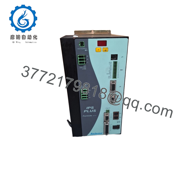
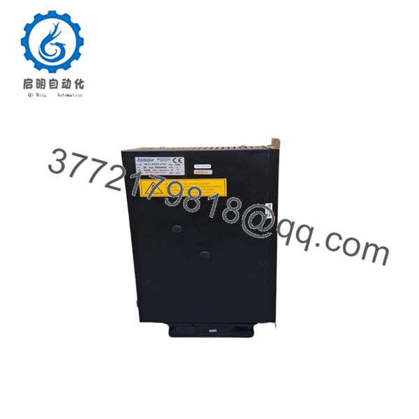
The Selema 08F1IPSP20715 is an industrial I/O interface module designed for signal acquisition and control within PLC and DCS architectures. It manages field-level inputs and outputs, enabling stable communication between sensors, actuators, and the control processor in continuous-process environments.
From a supply-chain standpoint, this unit is a New Surplus asset—critical for maintaining legacy systems where OEM production has slowed or stopped. Securing inventory now reduces exposure to lead time variability and avoids costly emergency sourcing. Compared to refurbished units, this approach lowers Total Cost of Ownership (TCO) by eliminating early-life failures and unplanned downtime.

- 08F1IPSP20715
- 08F1IPSP20715
5. Installation & Configuration Guide
Stage 1: Pre-Installation (Prep & Safety)
- Execute lock-out/tag-out (LOTO) on the control panel.
- Verify 24 V DC supply is isolated and discharged.
- Use an ESD wrist strap and grounded work surface.
- Take clear photos of wiring terminals and DIP switch settings.
- Label field wiring to prevent mis-termination.
Stage 2: Removal
- Release module locking clips or retaining screws.
- Pull the module straight out—avoid lateral force to protect backplane pins.
- Inspect connector pins for bending or carbonization.
Stage 3: Installation (Clone & Seat)
- Match DIP switch or jumper settings exactly to the original unit.
- Align the module with the guide rails and insert evenly.
- Apply firm, even pressure until fully seated.
- Secure locking mechanism.
Stage 4: Power-On & Testing
- Reapply 24 V DC power and monitor current draw.
- Check LED indicators: confirm RUN status, no ERR faults.
- Validate I/O signals via HMI or engineering software.
- Perform loop checks for critical channels.
6. Firmware/Software Versions & Upgrade Notes
- Recommended to match the firmware version of the existing system before replacement.
- Firmware mismatch can result in communication faults or I/O mapping errors.
- Example risk: newer firmware may not support legacy drivers or bus timing configurations.
- Avoid upgrading firmware during urgent replacement unless fully validated offline.
- Always document firmware version and configuration parameters prior to removal.
7. Frequently Asked Questions (FAQ)
Q1: Are these units truly new or previously installed?
These are New Surplus units. They originate from OEM production channels, retain original components, and show zero wear on connectors or circuitry.
Q2: Why is the price higher than refurbished alternatives?
Refurbished units carry hidden failure risks—aging capacitors and relays are common. A single failure can trigger downtime costs exceeding $50,000. New Surplus eliminates that exposure.
Q3: Is this module obsolete or still in production?
This model is likely in late lifecycle or EOL status. A Last-time-buy strategy is recommended to secure future maintenance coverage.
Q4: Can this module be hot-swapped?
No. Always power down the system before replacement to avoid backplane damage and data corruption.
Q5: Will I lose configuration or programming during replacement?
No onboard program storage is typically affected, but I/O addressing and parameters must match exactly. Always document settings before removal.
Q6: What warranty is provided?
Standard coverage is 12 months, significantly longer than the 30–90 days typically offered with non-new inventory.
Q7: What stocking strategy do you recommend?
For critical operations, maintain 1–2 units as buffer stock. Given lead time variability and EOL risk, this minimizes stock-out incidents and protects plant uptime.


