
 WhatsApp: +86 16626708626
 Email:
  Phone: +86 16626708626
Description
Key Technical Specifications
| Parameter | Value |
|---|---|
| Model / Part Number | 8141649.53 |
| Brand | SEW |
| Product Type | Main control board / PCB assembly |
| Application | SEW industrial automation / drive equipment |
| Board Function | Main electronic control and interface circuitry |
| Mounting | Internal equipment installation |
| Communication Interface | Not verified from OEM documentation |
| Supply Voltage | Not verified from OEM documentation |
| I/O Configuration | Not verified from OEM documentation |
| Dimensions | Not verified from OEM documentation |
| Operating Temperature | Not verified from OEM documentation |
| Weight | Not verified from OEM documentation |
A supplier listing specifically identifies 8141649.53 as a SEW main board and describes it as an internal motherboard-type assembly. Other industrial automation inventory pages also independently list the part number under SEW spare parts.
Engineering caution: Do not populate this page with generic PLC specifications such as 24 VDC, EtherNet/IP, Profibus, memory capacity, or I/O channel counts unless they are confirmed from the equipment documentation. Those specifications are not established for 8141649.53 by the sources I found.
Product Introduction
The SEW 8141649.53 is identified in industrial automation spare-parts listings as a main board used within SEW equipment. It is a board-level replacement component rather than a general-purpose PLC I/O module.
For replacement work, the complete part number is critical. Verify the installed board marking, equipment type, connector layout, PCB revision, and surrounding hardware before installation. Public listings provide limited technical data, so the machine-specific SEW documentation should take priority.
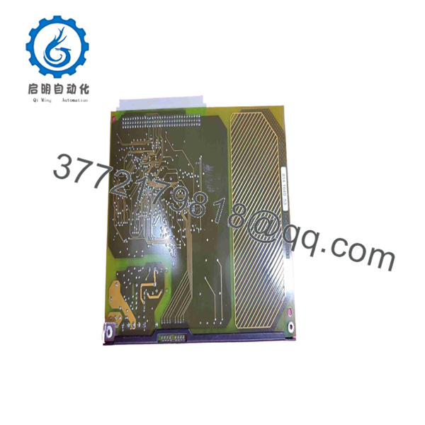
8141649.53
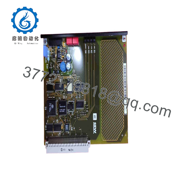
8141649.53
Installation & Configuration Guide
Stage 1: Pre-Installation Preparation — Approx. 10–15 minutes
⚠️ Safety First
- Notify operations and obtain approval for the equipment shutdown.
- Bring the driven machine to a defined safe state.
- Apply the site’s lockout/tagout procedure.
- Isolate incoming power to the SEW equipment.
- Wait at least 5 minutes for DC-link and other capacitors to discharge, or follow the specific SEW equipment manual if it specifies a longer period.
- Verify the absence of hazardous voltage with a properly rated multimeter.
Tools Required
- ESD wrist strap
- Digital multimeter
- PH1/PH2 screwdriver or correct SEW cabinet hardware driver
- Wire labels
- Smartphone or camera
- Torque-controlled screwdriver where terminal torque is specified
Data Backup
- Record the complete 8141649.53 marking.
- Photograph the board before removing anything.
- Photograph every connector and cable position.
- Record PCB revision and serial information if present.
- Photograph DIP switches, jumpers, rotary switches, and configuration links.
- Record the SEW drive/controller model containing the board.
- Save the existing drive parameters using the applicable SEW commissioning software before replacing the board.
⚠️ Do not treat 8141649.53 as a universal SEW control-board replacement. Confirm that the replacement belongs to the same equipment assembly and hardware revision.
Stage 2: Removing the Old Module — Approx. 10 minutes
- Remove the cabinet or equipment cover according to the applicable SEW manual.
- Confirm the DC bus has discharged.
- Photograph the entire board and connector arrangement before touching the wiring.
- Label each connector and cable.
- Disconnect connectors by their locking mechanism rather than pulling on the cable.
- Remove the board retaining screws or clips.
- Lift the PCB carefully without contacting exposed components.
- Inspect the board connector, mating connector, standoffs, and backplane for damage or contamination.
⚠️ Keep the removed 8141649.53 available until commissioning is complete. It provides the most reliable reference for jumper positions, connector orientation, and revision markings.
Stage 3: Installing the New Module — Approx. 10 minutes
- Put on the grounded ESD wrist strap.
- Compare the replacement board with the original side by side.
- Verify:
- 8141649.53 part number
- PCB revision
- Connector locations
- Connector keys
- DIP switch positions
- Jumper positions
- Mounting-hole arrangement
- Do not modify jumpers or configuration switches unless the machine documentation requires it.
- Position the board correctly on its guides or mounting posts.
- Install the retaining screws without over-tightening.
- Reconnect each connector according to the photographs and labels.
- Confirm every connector is fully seated and mechanically locked.
- Check that no cable is trapped beneath the PCB.
Self-Checklist
- Exact part number verified
- PCB revision checked
- Connectors matched
- Configuration switches matched
- Mounting hardware secured
- No loose cables
- No foreign objects inside cabinet
Stage 4: Power-On & Testing — Approx. 10–20 minutes
Pre-Power Check
- Inspect the board for loose screws, metal fragments, or displaced connectors.
- Verify the equipment’s supply wiring.
- Check for unintended shorts on accessible low-voltage rails where the equipment manual permits this test.
- Confirm protective earth connections.
Power-On Steps
- Energize the SEW equipment according to the approved startup procedure.
- Observe board and drive status LEDs.
- Check for hardware faults on the drive/controller display.
- Connect the appropriate SEW commissioning/diagnostic software.
- Verify that the controller recognizes the expected hardware.
- Compare stored parameters with the pre-replacement backup.
- Restore parameters only when the correct equipment configuration has been confirmed.
- Test control functions with the motor mechanically isolated where practical.
- Perform a controlled low-speed test.
- Return the machine to production only after all alarms and diagnostic states have cleared.
⚠️ If the replacement board powers up but the drive reports a hardware, configuration, or communication fault, stop commissioning. Check the PCB revision, board identity, parameter set, connector seating, and host equipment compatibility before attempting repeated power cycles.
Technical Pitfalls
❗ PCB revision mismatch: Two boards carrying the same base part number can potentially have different revisions or configuration requirements. Record the revision on the old board before ordering.
❗ Connector mismatch: Never assume that a connector with the same physical size has identical pin assignments. Compare the board layout and equipment wiring documentation.
❗ Parameter retention: Replacing a main electronic board can affect stored parameters depending on the SEW equipment architecture. Back up the existing configuration before removal.
❗ ESD damage: A PCB can be damaged before installation is complete. Use an ESD strap and handle the board by its edges.
❗ Wrong equipment family: The part number alone is not enough if several SEW assemblies use similar board construction. Verify the host equipment model and board revision.
Frequently Asked Questions (FAQ)
Q1. What is SEW 8141649.53?
Available industrial automation listings identify 8141649.53 as a SEW main board used as an internal electronic spare part. The available public information does not establish the exact host drive or controller family, so that should be confirmed from the equipment nameplate.
Q2. Is SEW 8141649.53 a PLC I/O module?
No evidence supports treating it as a conventional PLC digital or analog I/O module. It is listed as a main board / PCB assembly. Its actual function depends on the SEW equipment in which it is installed.
Q3. Can I replace 8141649.53 directly?
Only after confirming the host equipment and board revision. Compare the original and replacement boards, including connector arrangement, PCB revision, mounting points, switches, and jumpers. I would not approve a replacement based on the part number alone.
Q4. Will replacing 8141649.53 erase my drive parameters?
That depends on the specific SEW equipment architecture. Do not assume parameter retention. Back up the existing parameter set before removing the board and keep the original board until the replacement has been commissioned successfully.
Q5. Is 8141649.53 obsolete?
I could not verify a current OEM lifecycle statement for this exact part number. Because it appears primarily in industrial spare-parts listings rather than current product documentation, treat it as a potentially legacy spare until SEW documentation confirms otherwise.
Q6. Is a listed “new” 8141649.53 necessarily factory sealed?
No. A supplier’s “new” description does not by itself prove factory-sealed condition. For procurement, specify the required condition explicitly: Factory Sealed, New Original/New Surplus, or Refurbished and Tested. Request photographs of the actual PCB, label, packaging, and revision marking.
Q7. Why is technical information for 8141649.53 limited?
This is a relatively specific spare-part number, and the publicly indexed information I found is mainly supplier inventory data. One listing identifies it as a SEW main board but does not provide a reliable OEM electrical specification sheet. For a production replacement, the installed board label and the SEW equipment manual should take precedence over generic reseller descriptions.



