
 WhatsApp: +86 16626708626
 Email:
  Phone: +86 16626708626
Description
Key Technical Specifications
| Parameter | Value |
| Manufacturer | SEW-Eurodrive |
| Part / Revision Number | 822675X.13.17 (Designated on board assembly) |
| Product Line | MOVIDRIVE Compact / MOVITRAC Inverter Systems |
| Module Type | Internal Control & Option Card PCB Assembly |
| Operating Voltage | Internal DC Bus / Logic Rails via Drive Chassis |
| Interface Connections | Internal edge connector / Ribbon cable headers |
| Mounting Form Factor | Internal drive option slot / Control frame housing |
| Operating Temperature | 0°C to +50°C (32°F to 122°F) drive ambient rating |
| Compliance | CE, UL, RoHS compliant for industrial motion control |
| Dimensions / Weight | Approx. 160 mm × 100 mm × 25 mm | ~0.25 kg |
Product Introduction & Supply Chain Strategy
The SEW-Eurodrive 822675X.13.17 is an internal control processing card engineered for installation inside SEW MOVIDRIVE frequency inverters and servo controllers. Deployed in high-demand industrial application environments—including automated material handling conveyors, packaging lines, and crane hoist drives—it interfaces low-level logic processing directly with the drive power stage.
Maintaining the SEW 822675X.13.17 as a New Surplus spare is an essential strategy to minimize Total Cost of Ownership (TCO) across automated facilities. If an internal option card suffers electrical stress or logic failure, replacing the entire variable frequency drive causes significant unnecessary capital expense and extended system re-commissioning times. Holding a factory-sealed, uninstalled board enables rapid component-level recovery, eliminating the elevated failure rates and thermal fatigue associated with used or repaired electronics.
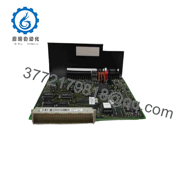
822675X.13.17
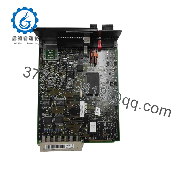
822675X.13.17
Installation & Configuration Guide
1.Stage 1: Pre-Installation (Prep & Safety):Perform complete power isolation and energy discharge.
Disconnect main line AC power to the SEW inverter chassis using standard Lock-Out/Tag-Out (LOTO) protocols. Wait at least 10 minutes to allow the DC bus capacitors to discharge completely below 50 V DC, and verify zero voltage with a calibrated meter. Put on a grounded ESD wrist strap before opening the drive enclosure.
2.Stage 2: Removal:Open chassis housing and extract damaged PCB.
Remove the drive front cover and protective ribbon cable retainers. Record the positioning of all onboard DIP switches, jumpers, and shield grounding clips. Unfasten the board retaining screws, carefully unplug internal ribbon cables by pressing their connector latches, and slide the 822675X.13.17 card out from its internal guide channels.
3.Stage 3: Installation (Clone & Seat):Replicate hardware jumpers and seat replacement board.
Set the DIP switch banks and jumper blocks on the New Surplus SEW 822675X.13.17 card to match the original board configuration exactly. Slide the card into the drive option slot, ensuring edge connectors line up squarely with the backplane header. Secure all mounting screws hand-tight to complete the ground reference path.
4.Stage 4: Power-On & Testing:Re-assemble enclosure and execute power diagnostic.
Re-attach internal ribbon cable connectors and replace the drive chassis front cover. Re-apply main AC line power to the inverter. Observe the drive status display: confirm that the unit boots into a ready state without displaying internal board fault codes (such as F14 or system bus errors).
Firmware/Software Versions & Upgrade Notes
- Drive Firmware Alignment: Verify that your main SEW MOVIDRIVE controller firmware is compatible with the 822675X revision index (.13.17). Mismatched control board revisions can trigger communication handshake faults during startup.
- MOVITOOLS Configuration: Parameter sets (such as motor maps and ramp times) reside in the drive’s primary EEPROM or control head module. After installing the replacement 822675X.13.17 board, connect via MOVITOOLS Motion Studio to verify parameter checksum integrity before running the motor under load.
- Component Replacement Warning: Never pull or insert option cards while line voltage or 24 V DC auxiliary control power is applied to the SEW inverter. Live insertion will permanently damage high-density microcontrollers on the option card logic bus.
Frequently Asked Questions (FAQ)
Q: What does New Surplus mean for an internal SEW board like the 822675X.13.17?
A: New Surplus signifies that the SEW 822675X.13.17 PCB assembly is 100% unused OEM stock. Sourced from project spare reserves, system integrator overstock, or unissued spare kits, it remains in pristine anti-static packaging and has never undergone thermal stress in a production drive chassis.
Q: Can I use the 822675X.13.17 board to repair a faulted SEW inverter rather than replacing the full drive?
A: Yes. Inverters often fault due to isolated control board failure while the heavy power stage (IGBTs and rectifiers) remains intact. Swapping in a New Surplus 822675X.13.17 board restores drive operation at a fraction of the cost of buying a complete replacement inverter assembly.
Q: Are there hardware DIP switches on the 822675X.13.17 board that require manual setting?
A: Depending on the specific drive family and option application, the board may feature DIP switches or header pins for addressing and terminating logic signals. You must duplicate the positions from your old board to ensure seamless operation.
Q: Is a complete firmware re-flash required after installing this card?
A: Generally, no. The host SEW drive controller recognizes the option card automatically upon power-up once hardware address switches match. However, running a diagnostic handshake via MOVITOOLS is recommended to ensure error-free data exchange.
Q: What warranty applies to this New Surplus board?
A: Every New Surplus SEW 822675X.13.17 control card is covered by a comprehensive 1 year seller warranty, protecting your purchase with full functional verification.



