
 WhatsApp: +86 16626708626
 Email:
  Phone: +86 16626708626
Description
Key Technical Specifications
| Parameter | Value |
| Input Channel | 1 Channel (Phase Marker / Tacho) |
| Input Sensor Type | Eddy current displacement sensor or magnetic pickup |
| Input Frequency Range | 0.1 Hz to 20,000 Hz (Application dependent) |
| Analog Output | 4-20 mA DC (Proportional to Speed) |
| Pulse Output | Buffered pulse output (TTL or Transistor) |
| Relay Outputs | Alert / Danger / OK Relays |
| Power Consumption | Approx. 5.5 W |
| Operating Temperature | 0 to +55 °C |
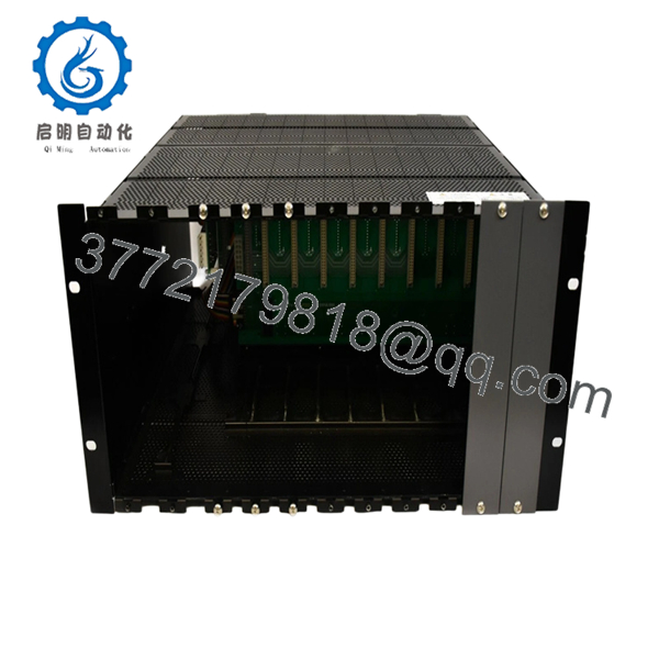
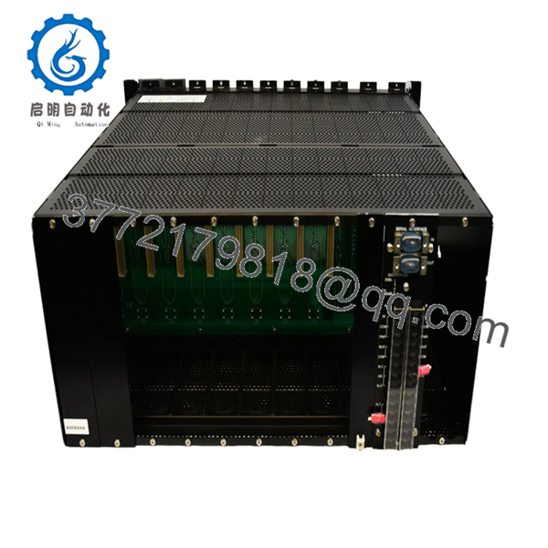
| Mounting | VM-5 Series System Rack Slot |
| Configuration | Field-configurable via internal DIP switches/jumpers |
Product Introduction
The Shinkawa VM-5H3-0 11 is a specialized phase marker module designed for the VM-5 Series Turbine Supervisory Instrumentation rack. It functions as the primary “clock” for rotating machinery analysis, converting raw pulses from a shaft keyway or gear tooth into a stabilized phase reference and a DC speed signal.
This module is indispensable for diagnostic operations, providing the phase trigger required for 1X vibration tracking and vector analysis. In my experience, the “11” suffix often denotes specific factory-set scaling or output configurations—always verify the full suffix against your system’s original design specifications to ensure timing accuracy across the backplane.
Installation & Configuration Guide
Stage 1: Pre-Installation Preparation
- ⚠️ Safety First: If this module is used for overspeed protection, verify that backup protection is active. Notify operations that speed-related trips may be affected during the swap.
- Tools Required: ESD wrist strap, small flat-head screwdriver, and a frequency generator (for bench calibration/verification).
- Data Backup: Document the speed range (RPM) and pulse-per-revolution (PPR) settings. Photograph the side-board jumpers on the existing module.
Stage 2: Removing the Old Module
- Loosen the two front-panel captive screws.
- Grasp the handle and slide the module out steadily.
- ⚠️ Note: Ensure you do not snag the backplane connector. Inspect the connector for carbon tracking or dust buildup, which often causes intermittent pulse failures.
Stage 3: Installing the New Module
- ESD Prep: Use a grounded wrist strap. These logic boards are sensitive to static discharge.
- Configuration Clone: Match the DIP switch positions for the input trigger level and the 4-20 mA scaling. This is critical: If the trigger level is off, the module will miss pulses or double-count, leading to erratic speed readings.
- Align the board with the rack guides and push until the connector seats fully.
- Secure the front-panel screws to ensure the module is grounded to the rack chassis.
Stage 4: Power-On & Testing
- Apply power. The “OK” LED should light up within seconds.
- Pulse Verification: Use an oscilloscope at the buffered output (if available) to verify a clean square-wave pulse.
- Speed Calibration: Compare the 4-20 mA output to the known shaft RPM. If the machine is at standstill, verify the “Zero” output is exactly 4.00 mA.
- Dry-run: Simulate a high-speed condition to verify the Alert/Danger relays transition at the correct setpoints.
- VM-5H3-0 11
- VM-5H3-0 11
Frequently Asked Questions (FAQ)
Q: Can this module be used for official Overspeed Protection?
A: While the VM-5H3-0 11 provides speed monitoring and relay outputs, check your plant’s SIL (Safety Integrity Level) requirements. Usually, a dedicated, redundant overspeed protection system is used for tripping, while the VM-5 series provides supervisory data and secondary alarms.
Q: What does the “11” at the end of the model number signify?
A: In Shinkawa’s nomenclature, these suffixes usually indicate specific factory modifications or hardware revisions related to output signal types or power supply variants. If your drawing calls for an “11,” do not substitute it with a “00” or “10” without checking the internal jumper map first.
Q: I’m getting an “OK” fault (Red LED) even though the sensor is fine. Why?
A: This is often a “Gap” issue. If the gap between the eddy current probe and the shaft is outside the linear range (typically -4V to -16V DC for Shinkawa probes), the VM-5H3-0 will trigger an OK fault to prevent false readings. Check your gap voltage at the terminal block.
Q: Is the 4-20 mA output isolated?
A: Most VM-5 modules offer isolated analog outputs to prevent ground loops between the TSI rack and the DCS. However, I always recommend using a signal isolator if you are running long cable lengths to a separate building.
Q: How do I set the “Pulses Per Revolution”?
A: This is typically handled via internal jumpers or DIP switches on the module’s PCB. If you are moving from a 1-pulse-per-rev keyway to a 60-tooth gear, you must reconfigure the module, or your speed reading will be off by a factor of 60.


