
 WhatsApp: +86 16626708626
 Email:
  Phone: +86 16626708626
Description
3. Key Technical Specifications
| Parameter | Value |
|---|---|
| Product Type | Interface PCB Board |
| System Compatibility | VM-7 Series racks (VM-761 / VM-762) |
| Function | Signal routing between modules and backplane |
| Input Channels | Up to 4 channels (system-dependent) |
| Input Impedance | Approx. 50 kΩ |
| Output Type | Buffered analog output (voltage/current) |
| Output Range | 1–5 VDC / 4–20 mA |
| Insulation Resistance | ≥10 MΩ @ 100 VAC |
| Transducer Supply | −24 VDC / +24 VDC sensor excitation |
| Mounting | Installed within VM-7 rack system |
| Application | Turbine/compressor protection systems |
| Lifecycle | Legacy system component (limited OEM availability) |
4. Product Introduction & Supply Chain Strategy
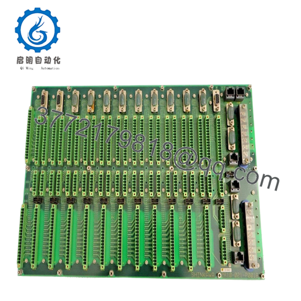
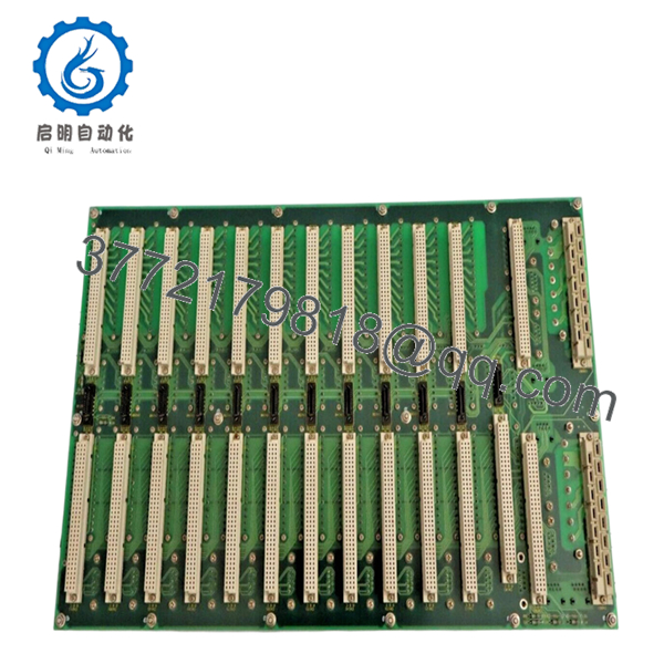
The SHINKAWA VM-7 2R10-021-P001B is an internal interface PCB used within VM-7 machinery monitoring systems. It handles signal distribution, sensor input routing, and communication between monitoring modules and the rack backplane in turbine supervisory and protection systems.
From an inventory strategy standpoint, this is a hidden single-point-of-failure component. Unlike front-facing modules, PCB failures disable entire racks. Given VM-7 system maturity and declining OEM support, lead time variability is unpredictable. A controlled last-time-buy strategy with minimum buffer stock (1–2 units per site) is essential to avoid extended outages and inflated emergency procurement costs.
5. Installation & Configuration Guide
Stage 1: Pre-Installation (Prep & Safety)
- Execute full Lock-Out/Tag-Out (LOTO).
- Power down rack and verify zero voltage.
- Use ESD wrist strap—PCB is highly sensitive.
- Document:
- Cable harness connections
- Slot and PCB orientation
- Grounding points
Stage 2: Removal
- Remove rack or access rear panel depending on configuration.
- Disconnect ribbon cables and connectors carefully.
- Unscrew PCB mounting points evenly.
- Extract board without flexing to avoid micro-cracks.
Stage 3: Installation (Clone & Seat)
- Install PCB in identical orientation.
- Reconnect all harnesses firmly—no partial seating.
- Verify grounding continuity.
- Ensure no cable strain or pin misalignment.
Stage 4: Power-On & Testing
- Perform insulation check before energizing.
- Apply power and confirm:
- POWER-OK LED at rack level
- No system-wide alarm triggers
- Validate signal transmission:
- Sensor input readings stable
- Output signals correctly scaled (4–20 mA / 1–5 V)

- VM-7 2R10-021-P001B
- VM-7 2R10-021-P001B
6. Firmware/Software Versions & Upgrade Notes
- This PCB does not contain user-updatable firmware; it operates as a hardware interface layer.
- Critical dependency:
- Must match VM-7 rack revision and installed module set.
- Compatibility risks:
- Mixing different PCB revisions can introduce signal noise or communication instability.
- Best practice:
- Maintain identical hardware revision across redundant systems.
- Avoid introducing newer revisions without full system validation.
7. Frequently Asked Questions (FAQ)
Q1: Is this PCB truly new? Most market listings show used boards.
Yes. Secondary markets are dominated by pulled boards. We supply New Surplus units only—unused, no thermal stress, no solder repairs, and fully traceable.
Q2: Why is a PCB considered critical inventory?
Because it is a non-redundant infrastructure layer. If it fails, multiple monitoring channels go offline simultaneously.
Q3: Why not use refurbished boards?
Refurbished PCBs often have latent issues—micro-cracks, aged capacitors, or prior thermal cycling. These failures are unpredictable and can shut down entire monitoring systems.
Q4: Is this part obsolete?
Yes. VM-7 systems are still deployed globally, but OEM production is limited. This is a textbook EOL lifecycle component requiring proactive stocking.
Q5: What stocking level do you recommend?
- Minimum: 1 unit per plant (buffer stock)
- Maximum: 2 units with cross-site sharing strategy
Q6: Can this be replaced online?
No. Full shutdown is required. Hot replacement risks system-wide signal corruption and false trips.
Q7: What QC and warranty are included?
Each unit undergoes:
- Serial traceability verification
- Visual and electrical inspection
- Insulation and continuity testing
- Controlled packaging (ESD-safe)
Warranty: 12 months.


