
 WhatsApp: +86 16626708626
 Email:
 Phone: +86 16626708626
Description
Core Product Summary
The Shinkawa VM-701BNB1TRPTB1 is a VM-701B Vibration/Displacement Monitor Module configured for the Shinkawa VM-7 monitoring system. It continuously monitors up to four vibration or displacement channels from rotating machinery and provides alarm, recorder, and relay outputs for machinery protection and condition-monitoring applications.
The /NB1 configuration is a non-incendive version rated for CSA C/US Class I, Division 2, Groups A, B, C, and D installations. The /TRP code denotes the tropical specification, while /TB1 includes the transducer-input, recorder-output, and contact-output terminal-block plugs. The module installs in a VM-7 Series instrument rack and is configured through the VM-7 system rather than as a stand-alone controller.
Key Technical Specifications
| Parameter | VM-701BNB1TRPTB1 |
|---|---|
| Manufacturer | Shinkawa Electric Co., Ltd. |
| Base model | VM-701B Vibration/Displacement Monitor Module |
| System family | VM-7 Monitoring System |
| Configuration | VM-701B /NB1 /TRP /TB1 |
| Input channels | 4 vibration/displacement input points |
| Input impedance | Approximately 50 kΩ; approximately 250 Ω for current-signal input |
| Supported displacement-vibration transducers | FK-202F, FK-452F, FK-302F, VK-202A, VK-452A, VK-202P, VK-302P, VC-020 |
| Supported velocity transducers | CV-88, CV-87, CV-86 |
| Supported acceleration transducers | CA-302, CA-72 |
| Voltage/current input | -10 V to +10 V voltage signal; 4 mA to 20 mA current signal |
| Recorder outputs | 4 points; 1–5 V, 4–20 mA, 0–5 V, or 0–10 V |
| Current-output load | Maximum 600 Ω |
| Relay outputs | 6 configurable dry-contact SPDT relays |
| Relay contact rating | 250 VAC / 5 A or 30 VDC / 5 A |
| Transducer supply, proximity type | -24 VDC ±10%, 25 mA maximum |
| Transducer supply, piezoelectric type | +24 VDC ±10%, 4 mA constant current |
| Operating temperature | 0 to +65°C; 0 to +60°C in explosion-proof construction |
| Storage temperature | -30 to +85°C |
| Relative humidity | 20 to 95% RH, non-condensing |
| Module power consumption | Less than 15 W |
| Mass | Maximum 1.0 kg |
| Configuration code | /NB1 non-incendive; /TRP tropical specification; /TB1 terminal-block accessory set |
Engineering Selection Highlights
- The VM-701B provides four vibration/displacement input channels, allowing one module to monitor multiple sensor points on a machine train.
- The
/NB1suffix identifies a non-incendive construction for CSA C/US Class I, Division 2, Groups A, B, C, and D locations, which is relevant when the module is used in classified plant areas. - The
/TRPtropical specification should be matched to the environmental requirements of the installation. - The
/TB1accessory set includes two 15-pin transducer-input terminal-block plugs, two 6-pin recorder-output terminal-block plugs, and one 18-pin contact-output terminal-block plug. - The module accepts FK/VK eddy-current displacement transducers, CV velocity transducers, CA acceleration transducers, and selected voltage or current signals, so the installed sensor type determines the applicable monitoring configuration.
- Six field-configurable SPDT relay outputs support alarm and protection logic; each relay can be set for normally de-energized or normally energized operation.
- The module requires a VM-7 Series instrument rack and rack power supply; it is not a stand-alone panel-mounted monitor.
System Compatibility & Integration Requirements
| Item / Dependency | Verified Compatibility or Requirement | Practical Note |
|---|---|---|
| Monitoring system | Shinkawa VM-7 Monitoring System | The module operates as part of a VM-7 rack-based monitoring system. |
| Instrument rack | VM-761B or VM-762B instrument rack | Rack selection determines the rear connector arrangement and terminal-block layout. |
| Power supply | VM-75□B power supply module | Confirm that the rack power supply has adequate input power for the installed module configuration. |
| Transducer inputs | FK, VK, CV, CA, VC, and VM-21P devices as listed by Shinkawa | Sensor type must match the configured measurement function and input range. |
| Recorder outputs | Four assignable outputs; 1–5 V, 4–20 mA, 0–5 V, or 0–10 V | Current mode supports up to 600 Ω load resistance. |
| Relay outputs | Six SPDT dry contacts | Contact logic and energization method are field changeable. |
| Terminal accessories | /TB1 includes transducer-input, recorder-output, and contact-output terminal-block plugs |
The D-sub monitor-output plug and hood are not included with /TB1. |
| Phase-marker function | Available only when the /PM1 option is specified |
This model identification does not include /PM1, so phase-marker input should not be assumed. |
| Analysis function | Available only with the /ALY option |
This model identification does not include /ALY, so analysis and diagnostic functions should not be assumed. |
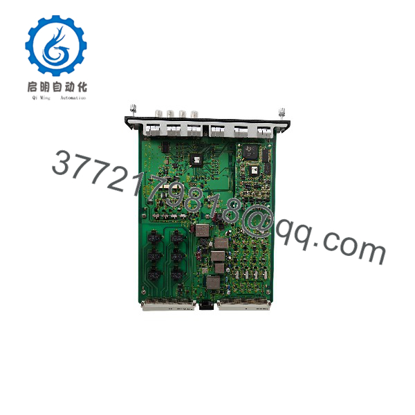
VM-701BNB1TRPTB1
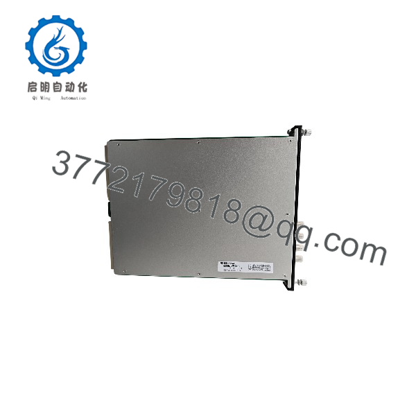
VM-701BNB1TRPTB1
Dimensions, Mounting & Connection Notes
- The module body has a maximum mass of 1.0 kg.
- It mounts in a Shinkawa VM-7 Series instrument rack; the VM-701B occupies a monitor-module slot in the rack configuration.
- The
/TB1accessory set includes:- Two 15-pin transducer-input terminal-block plugs.
- Two 6-pin recorder-output terminal-block plugs.
- One 18-pin contact-output terminal-block plug.
- The monitor output is available at a front BNC connector and through the rear monitor-output connector.
- The pulse output is provided at the front BNC connector.
- The synchronized-signal output is routed through rear terminals: D5/D6 on a VM-761B rack or pins 13 and 14 of the 15-pin D-sub connector on a VM-762B rack.
- The module face plate is ABS, the sheet is polyester tough top, and the base plate is aluminum alloy.
Detailed Product Overview
The Shinkawa VM-701BNB1TRPTB1 is a configured version of the VM-701B Vibration/Displacement Monitor Module for the Shinkawa VM-7 Monitoring System. Its role is to convert transducer signals from rotating machinery into monitored values, alarm states, recorder signals, and relay contacts that can support both operational condition monitoring and protective actions.
Each module provides four input points. Depending on configuration, it accepts displacement-vibration signals from FK or VK eddy-current transducers, velocity signals from CV transducers, acceleration signals from CA transducers, and selected voltage or current inputs. This allows the same module platform to serve different measurement duties across a machine train, provided the installed sensor, monitoring range, rectification method, and filter settings are configured consistently.
For vibration monitoring, the module supports RMS, peak-to-peak, and low-speed peak-to-peak rectification. RMS rectification is applicable to displacement, velocity, and acceleration measurements; peak-to-peak rectification is applicable to displacement vibration; and the low-speed peak-to-peak method applies to displacement-transducer inputs for displacement-vibration measurement. Filter settings are configurable within the ranges documented for each rectification method, which lets the monitoring bandwidth be matched to the machine and measurement requirement.
For displacement monitoring, the module provides high and low alert and danger setpoints, zero-shift adjustment, and addition or subtraction operations between adjacent channel pairs. These functions support applications such as axial position and differential-expansion-related monitoring when configured with appropriate displacement inputs.
The module includes four recorder outputs, each assignable to a measurement channel. Output formats include 1–5 V, 4–20 mA, 0–5 V, and 0–10 V. The 4–20 mA output includes a downscale burnout function, providing a defined output state when a fault condition occurs. Six SPDT relay contacts provide configurable alarm logic, with field-changeable normally de-energized or normally energized operation.
The /NB1 suffix is central to this exact part number: it identifies non-incendive construction for CSA C/US Class I, Division 2, Groups A, B, C, and D. The /TRP suffix identifies the tropical specification. The /TB1 suffix defines the supplied terminal-block accessory package, which covers the transducer, recorder, and contact-output wiring connections.
This module must be installed in a compatible VM-7 instrument rack and powered through the VM-7 rack power-supply architecture. It is configured as part of the VM-7 system; the exact measurement ranges, alarm setpoints, relay logic, sequence settings, suppression settings, and output assignments must be established for the installed machinery and transducer arrangement.
Applications & System Role
The VM-701BNB1TRPTB1 functions as a machinery protection and condition-monitoring module within a Shinkawa VM-7 rack system. It conditions signals from machine-mounted vibration and displacement transducers, calculates the selected monitoring value, compares it with configurable alarm setpoints, and operates relay outputs for alert, danger, and module-health functions.
Its four input channels make it suitable for shaft relative vibration, casing-related vibration measurement configurations, axial position, and displacement monitoring where the corresponding Shinkawa transducer and monitoring range are configured. The recorder outputs provide proportional signals for plant recorders, DCS inputs, or other monitoring systems, while the relay contacts interface with machinery protection circuits.
The /NB1 non-incendive rating and /TRP tropical specification make this exact configuration relevant where the VM-7 rack is installed in a classified-area application and requires the specified environmental construction.
FAQ
What is the Shinkawa VM-701BNB1TRPTB1?
It is a Shinkawa VM-701B Vibration/Displacement Monitor Module configured as /NB1 /TRP /TB1 for the VM-7 Monitoring System.
How many input channels does it provide?
It provides four vibration/displacement input points.
Which sensors can it accept?
It supports specified Shinkawa FK and VK displacement-vibration or displacement transducers, CV velocity transducers, CA acceleration transducers, VC transducers, and VM-21P voltage or current inputs, subject to the configured measurement function.
What does the /NB1 suffix mean?
It identifies non-incendive construction for CSA C/US Class I, Division 2, Groups A, B, C, and D.
What does /TB1 include?
It includes two 15-pin transducer-input terminal-block plugs, two 6-pin recorder-output terminal-block plugs, and one 18-pin contact-output terminal-block plug.
Does this model include a phase-marker input?
No. The phase-marker function requires the /PM1 option, which is not part of the VM-701BNB1TRPTB1 identification.
Does this model include the analysis function?
No. The analysis function requires the /ALY option, which is not included in this model identification.
Where is the module installed?
It is installed in a Shinkawa VM-7 Series instrument rack and operates with the VM-7 rack power-supply and system configuration.



