
 WhatsApp: +86 16626708626
 Email:
  Phone: +86 16626708626
Description
Key Technical Specifications
| Parameter | Value |
| Output Channels | 18 Channels (Programmable Logic) |
| Contact Type | Dry Contact (SPST) |
| Contact Rating | 250V AC / 5A; 30V DC / 5A |
| Excitation Mode | Normally De-energized / Normally Energized (Jumper selectable) |
| Logic Elements | Up to 255 elements per alarm relay |
| Slot Requirement | Specifically restricted to Slot 11 of the VM-7 rack |
| Power Consumption | ≤ 15 W |
| Operating Temp | 0 to +65 °C (Standard); 0 to +60 °C (Non-incendive) |
| Connector Type | /TB1: PHOENIX CONTACT FRONT-MC-1.5/18-STF-3.81 (2 pcs) |
| Weight | Max. 1.0 kg |
Product Introduction
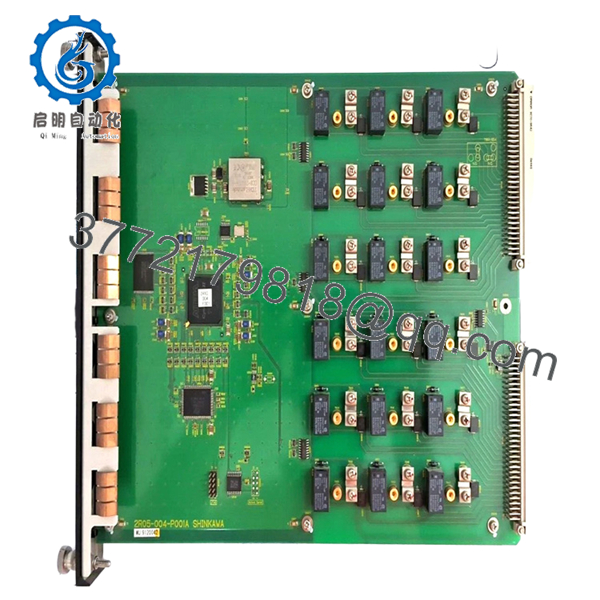
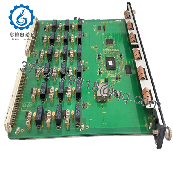
The Shinkawa VM-721B-TB1 is an 18-channel relay expansion module for the VM-7 Series Condition Monitoring System. While individual VM-7 monitor modules (like the VM-701B) contain internal relays, the VM-721B is used when complex, plant-wide voting logic (such as 2-out-of-3) is required across multiple measurement parameters.
This specific version, designated with the TB1 suffix, comes supplied with the necessary 18-pin Phoenix Contact terminal block plugs for immediate wiring. It is fully compliant with API 670 standards and is typically installed in Slot 11 of the VM-7 instrument rack to serve as the central hardware interface for emergency shutdown (ESD) systems.

- VM-721B-TB1
- VM-721B-TB1
Installation & Configuration Guide
Stage 1: Pre-Installation Preparation
- ⚠️ Safety First: This module typically drives trip solenoids or master alarms. Ensure the machine protection string is safely bypassed and the control room is notified.
- Tools Required: ESD wrist strap, small flat-head screwdriver (for terminal screws), and a laptop with VM-772B Device Config software.
- Data Backup: Since relay logic is software-defined, export the existing configuration file (.v7c) from the rack via the USB service port before swapping.
Stage 2: Removing the Old Module
- Disconnect the two 18-pin Phoenix terminal plugs from the rear (or front, depending on rack orientation).
- Loosen the captive screws on the black ABS faceplate.
- Pull the module straight out.
- ⚠️ Note: The VM-721B is a “System Level” card. Removing it may trigger a “SYS-OK” fault on the rack communication module.
Stage 3: Installing the New Module
- ESD Prep: Ground yourself. The logic chips on the VM-7 series are high-density and sensitive to static.
- Slot Verification: The VM-721B must be installed in Slot 11. If installed in any other slot, the “ACTIVE” LED will flash, and the logic will not execute.
- Check internal jumpers if you need to switch between Normally Open (N.O.) and Normally Closed (N.C.) hardware states.
- Slide into Slot 11 and tighten the faceplate screws.
Stage 4: Power-On & Testing
- Apply power. The “ACTIVE” LED should be solid green.
- Logic Upload: Connect your PC to the rack’s USB port. Use VM-772B software to upload the saved relay logic to the new module.
- Forcing Test: Use the software’s “Forcing” function to manually trigger each of the 18 relays. Verify continuity at the terminal block for every channel.
- Final Check: Ensure the “SYS-OK” relay on the power supply module is energized, indicating the rack recognizes the new relay board.
Frequently Asked Questions (FAQ)
Q: Can I install two VM-721B modules in a single rack for 36 relays?
A: No. The VM-7 system architecture only supports one VM-721B module per rack, and it is hard-coded for Slot 11. If you need additional relays, you should use multiple VM-722B (9-channel) modules, which can be placed in other slots.
Q: Does the TB1 suffix refer to a different PCB?
A: No, the internal electronics are identical to a standard VM-721B. The “TB1” code specifically ensures that the shipping box includes the 18-pin mating connectors. Without this suffix, you might receive the card without the green terminal plugs.
Q: What happens to the relays if the rack loses power?
A: This depends on your jumper settings. If set to “Normally Energized” (fail-safe), the relays will drop out and trigger a trip upon power loss. I’ve spent many nights debugging “mystery trips” that were just momentary power dips on racks set to normally energized logic.
Q: Do I need special software to set the alarm logic?
A: Yes. Unlike the older VM-5 series which used jumpers, the VM-721B requires the VM-772B Device Config software. You cannot program the AND/OR logic via the front panel.
Q: Are the contacts rated for direct motor starter control?
A: At 5A, they are quite beefy for a signal card, but I always recommend using an interposing relay for high-inductive loads like large solenoid valves or motor starters to prevent contact pitting and extend the life of the module.


