WhatsApp: +86 16626708626
 Email:
 Phone: +86 16626708626
Description
Core Product Summary
The SHINKAWA VM-742B1-1 is a network communication module for the VM-7 Monitoring System. It provides fieldbus connectivity using Modbus/TCP on Port A, with Port B blank, and is intended for installation in the upper C1 slot of a compatible instrument rack.
This module enables transmission of measurement values, gap data, alarm statuses, and related system information from the VM-7 rack to host systems such as DCS or PLC platforms. It supports redundant network configurations when a second module is installed and operates within the environmental and power limits defined for the VM-7 series.
Key Technical Specifications
| Parameter | Specification |
|---|---|
| Product type | Network Communication Module |
| System series | VM-7 Monitoring System |
| Model configuration | VM-742B1-1 (Slot C1, Port A: Fieldbus Modbus/TCP, Port B: Blank) |
| Primary protocol | Modbus/TCP |
| Network interface | Ethernet 10Base-T / 100Base-TX |
| Connector | RJ-45 (on rear panel of VM-76□B rack) |
| Default IP address | 192.168.8.1 |
| Default port | 502 |
| Indicators | ACTIVE 1 / COMM 1 (green LEDs) |
| Power consumption | Less than 15 W (module alone) |
| Operating temperature | 0 to +65 °C (0 to +60 °C for explosion-proof construction) |
| Storage temperature | −30 to +85 °C |
| Relative humidity | 20 to 95 % RH (non-condensing) |
| Mass | Max. 0.5 kg |
| Face plate material | ABS (black) |
Detailed Product Overview
The SHINKAWA VM-742B1-1 serves as the network communication interface within the VM-7 Monitoring System, a modular platform designed for protective monitoring of critical rotating machinery in accordance with API 670 and related ISO requirements. Its primary role is to move measurement data, gap values, danger/alert/OK alarm statuses, bypass conditions, and (when analysis options are present on monitor modules) selected analyzed data from the instrument rack to external host systems.
Configured specifically for Slot C1 with Port A dedicated to Modbus/TCP and Port B left blank, the module provides a straightforward single-port fieldbus connection. Data items transmitted include live measurement values, gap, alarm status bits, filter status, power-OK indication, and, when the corresponding analysis boards are installed on vibration or displacement monitor modules, amplitude and phase information at selected harmonic components. The module also accepts date-and-time synchronization data from the host.
Up to two network communication modules may be installed in a single rack (one in C1 and one in C2). This arrangement supports redundant host communication paths, reducing the risk of monitoring interruption caused by a single network or module failure. Front-panel ACTIVE and COMM LEDs give immediate visual indication of module readiness and communication activity.
The module draws power from the rack backplane and consumes less than 15 W. It is rated for continuous operation from 0 °C to +65 °C (restricted to +60 °C under explosion-proof construction conditions) and can be stored between −30 °C and +85 °C. Humidity tolerance is 20–95 % RH non-condensing. Construction uses an ABS face plate, polyester sheet, and aluminum-alloy base plate, with a maximum mass of 0.5 kg.
Integration requires a compatible VM-76□B instrument rack (terminal-block or D-sub connector versions). The RJ-45 network connector is located on the rear panel of the rack, not on the module itself. Configuration of IP address, subnet, and related parameters is performed through the system’s device-configuration tools. Optional security features meeting Achilles Level 2 criteria are available on the series when the corresponding security-function codes are selected at order time.
In practical plant architecture the VM-742B1-1 therefore functions as the bridge between the local vibration, displacement, temperature, and related monitor modules and the plant control or asset-management network, enabling both protective alarm signaling and longer-term condition-data transfer.
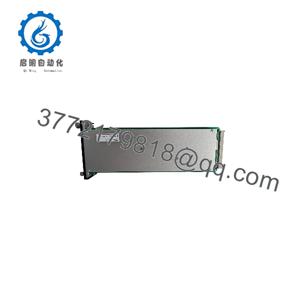
VM-742B1-1
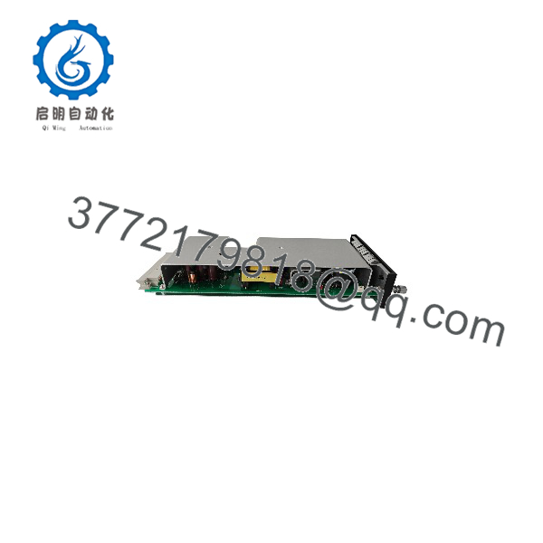
VM-742B1-1
System Compatibility & Integration Requirements
| Item / Dependency | Verified Compatibility or Requirement | Practical Note |
|---|---|---|
| System family | VM-7 Monitoring System | Must be installed in a VM-7 series instrument rack |
| Instrument rack | VM-76□B (VM-761B or VM-762B) | RJ-45 network connectors are provided on the rack rear panel |
| Slot position | Slot C1 (upper) | Specific to the “1-1” model code; C2 versions use different coding |
| Network protocol | Modbus/TCP (Port A) | Port B is blank on this exact model |
| Redundancy | Second module in Slot C2 | Two modules required for redundant host communication |
| Power supply | Rack backplane via VM-75□B power supply module(s) | Module itself consumes <15 W |
| Host systems | DCS, PLC, or infiSYS analysis stations | Transmits measurement, gap, alarm, and optional analyzed data |
| Configuration tools | System device-configuration software | Used for IP address, subnet, and related network settings |
Dimensions, Mounting & Connection Notes
- Mass: maximum 0.5 kg
- Mounting: front-insertion module for VM-76□B instrument rack, Slot C1
- Network connection: RJ-45 Ethernet connector located on the rear panel of the instrument rack
- Indicators: front-panel green ACTIVE and COMM LEDs
- Environmental installation limits: operating 0 to +65 °C (0 to +60 °C explosion-proof construction), storage −30 to +85 °C, 20–95 % RH non-condensing
FAQ
What is the SHINKAWA VM-742B1-1?
It is a network communication module for the VM-7 Monitoring System that provides Modbus/TCP fieldbus connectivity from the instrument rack to host systems.
Which system does the VM-742B1-1 belong to?
It belongs to the SHINKAWA VM-7 series machinery monitoring and protection system.
What communication protocol does the VM-742B1-1 use?
Port A is configured for Fieldbus Modbus/TCP; Port B is blank on this model.
Where is the VM-742B1-1 installed?
It is installed in Slot C1 (upper position) of a compatible VM-76□B instrument rack.
Can the network communication be made redundant?
Yes. Installing a second network communication module in Slot C2 provides redundant host communication paths.
What data does the module transmit?
It transmits measurement values, gap data, danger/alert/OK alarm statuses, bypass statuses, and, when analysis options are present, selected analyzed vibration data.
What are the operating temperature limits?
Operating temperature is 0 to +65 °C (restricted to 0 to +60 °C for explosion-proof construction).