
 WhatsApp: +86 16626708626
 Email:
  Phone: +86 16626708626
Description
Key Technical Specifications
| Parameter | Specification |
|---|---|
| Part Number | 6GK5202-2BB00-2BA3 |
| Manufacturer | Siemens |
| Product Family | SCALANCE X-200IRT managed |
| Exact Product | SCALANCE X202-2IRT |
| Ethernet Ports | 2 × 10/100 Mbps RJ45 |
| Fiber Ports | 2 × 100 Mbps multimode BFOC |
| Fiber Connector | BFOC/ST-style optical interface |
| Network Type | Industrial Ethernet |
| PROFINET | PROFINET IO Device |
| IRT | Integrated Isochronous Real-Time Ethernet support |
| Redundancy | Redundancy Manager integrated |
| Management | CLI, Web-based management, MIB |
| Configuration | STEP 7 supported |
| Supply Voltage | 24 V DC nominal; 18–32 V DC |
| Maximum Current | 0.3 A |
| Power Dissipation | 6 W at 24 V DC |
| Operating Temperature | -40 to +60 °C |
| Storage Temperature | -40 to +70 °C |
| Relative Humidity | Up to 95% at 25 °C, non-condensing |
| Protection | IP30 |
| Dimensions | 60 × 125 × 124 mm |
| Net Weight | 0.78 kg |
| Mounting | 35 mm DIN rail, wall, S7-300 rail |
| C-PLUG | Supported as optional removable storage |
Siemens identifies 6GK5202-2BB00-2BA3 as the SCALANCE X202-2IRT managed Industrial Ethernet switch, with two 10/100 Mbps RJ45 ports and two 100 Mbps multimode BFOC fiber ports. The device supports PROFINET IO, network management, and an integrated Redundancy Manager.
The Siemens data sheet specifies 24 V DC external power, an 18–32 V DC operating range, 0.3 A maximum consumption, 6 W power loss at 24 V DC, -40 to +60 °C operation, IP30 protection, and 60 × 125 × 124 mm dimensions.
Product Introduction
The Siemens SCALANCE X202-2IRT, part number 6GK5202-2BB00-2BA3, is a managed Layer 2 Industrial Ethernet switch intended for PROFINET and industrial automation networks requiring IRT capabilities. Its four network interfaces combine copper RJ45 connections with multimode BFOC fiber interfaces.
The switch supports web-based management, CLI, MIB functions, STEP 7 configuration, and an integrated Redundancy Manager. Its dual fiber interfaces make it suitable for industrial network topologies where electrical isolation and longer optical links are required.
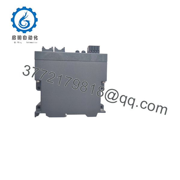
6GK5202-2BB00-2BA3
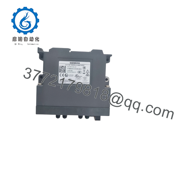
6GK5202-2BB00-2BA3
Installation & Configuration Guide
Stage 1 — Pre-Installation Preparation — 5–10 min
- Apply LOTO and follow the site’s industrial-network maintenance procedure.
- Confirm the replacement nameplate reads 6GK5202-2BB00-2BA3.
- Verify that the existing network requires the SCALANCE X202-2IRT feature set.
- Record:
- RJ45 port assignments
- Fiber RX/TX connections
- PROFINET device name
- IP address
- Network topology
- Redundancy configuration
- Back up the existing switch configuration where applicable.
- Photograph the existing switch, fiber connections, DIP/selector settings if fitted, and status LEDs.
- Prepare:
- ESD protection
- PH1 screwdriver
- Digital multimeter
- Fiber inspection/cleaning equipment
- Ethernet patch cable
- Laptop with the appropriate Siemens engineering/diagnostic software
- Labels and camera
- Verify the replacement’s hardware/firmware revision before installation.
⚠️ Siemens has published security advisories affecting the SCALANCE X202-2IRT family. Siemens recommends applying the applicable firmware updates and mitigations for affected versions. Check the exact firmware revision of the replacement before connecting it to a production network.
Stage 2 — Removing the Existing Switch — ~5 min
- Place the affected network segment into the approved maintenance state.
- Record switch LEDs and network alarms.
- Label each RJ45 and optical connection.
- Record the exact fiber RX/TX orientation.
- Disconnect network cables carefully.
- Disconnect the 24 V DC supply.
- Release the DIN-rail or mounting mechanism.
- Remove the switch without stressing the fiber cables.
- Inspect the mounting area and power wiring.
- Keep the old switch available until network commissioning is complete.
⚠️ Do not disconnect or reconnect optical connectors with contaminated ferrules. Clean and inspect the fiber interfaces before commissioning.
Stage 3 — Installing the 6GK5202-2BB00-2BA3 — 5–10 min
- Verify the exact MLFB: 6GK5202-2BB00-2BA3.
- Verify the replacement hardware revision and firmware.
- Mount the switch securely on the appropriate rail or mounting surface.
- Verify the 24 V DC supply polarity and voltage.
- Connect the redundant/required supply arrangement according to the installation documentation.
- Reconnect the two RJ45 interfaces.
- Reconnect the two BFOC multimode fiber interfaces using the recorded RX/TX arrangement.
- Do not force optical connectors into place.
- Verify cable routing and strain relief.
- Confirm that the switch is mechanically secure before energizing.
The data sheet specifies 35 mm DIN-rail, wall, and S7-300 rail mounting, with an IP30 compact enclosure measuring 60 × 125 × 124 mm.
Installation Self-Check
- 6GK5202-2BB00-2BA3 verified
- Hardware/firmware revision recorded
- 24 V DC supply checked
- assignments verified
- BFOC fiber RX/TX orientation verified
- Fiber connectors inspected
- Network configuration backed up
- Mounting secure
Stage 4 — Power-On & Testing — 10–15 min
- Measure the DC supply before energizing the switch.
- Apply power according to the approved network-maintenance procedure.
- Check the switch LEDs.
- Verify the Ethernet link on each connected port.
- Verify both optical interfaces.
- Confirm the switch is visible to the engineering/management system.
- Verify the assigned IP configuration.
- Confirm the PROFINET device name and controller association.
- Verify the Redundancy Manager configuration if used.
- Check for network diagnostics or topology alarms.
- Perform controlled communication tests with representative PLC/PROFINET devices.
- Do not return the network to full production service until PROFINET and redundancy behavior have been verified.
Supplier Acceptance / QC Checklist
For a shutdown-critical spare, the supplier acceptance record should include:
- Exact 6GK5202-2BB00-2BA3 identification
- Hardware revision and serial-number traceability
- Visual inspection of and BFOC interfaces
- 24 V DC power-up verification
- Copper-port link test
- Fiber-port link test
- Management-interface accessibility test
- PROFINET communication test where suitable equipment is available
- Firmware identification
- Configuration-memory/C-PLUG inspection where applicable
- Final QC inspection and ESD-safe packaging
A useful test report should identify firmware revision and actual port-level testing, not simply state that the switch powers on.
Technical Pitfall & Survival Guide
1. Do Not Confuse the X202-2IRT With the X202-2P IRT
Siemens has several visually similar SCALANCE X200IRT models. 6GK5202-2BB00-2BA3 is the with two and two multimode BFOC interfaces. The X202-2P IRT uses a different MLFB.
2. Fiber Type Matters
The specified optical interfaces are 100 Mbps multimode BFOC. Do not replace the fiber hardware based solely on connector appearance. Verify the installed fiber type and optical budget.
3. Firmware Security Is a Real Maintenance Issue
Siemens ProductCERT has published vulnerabilities affecting the SCALANCE X200/X200IRT family, including . A replacement with old firmware may restore communications while leaving the network exposed to known vulnerabilities. Check the exact installed firmware against current Siemens security guidance before production use.
4. Redundant Power Does Not Mean Unlimited Power Inputs
The device supports redundant voltage supply, but the actual supply wiring must follow the Siemens terminal arrangement. Verify both supply paths independently during commissioning.
5. C-PLUG Configuration
The supports an optional C-PLUG removable configuration-storage device. If the existing switch uses a C-PLUG, determine whether the replacement requires transfer of the existing configuration before energizing.
6. Check the Hardware Revision
The exact MLFB is essential, but it is not the only procurement variable. For a legacy industrial switch, record the hardware revision, firmware version, C-PLUG status, and configuration before replacement.
Frequently Asked Questions (FAQ)
1. What is Siemens 6GK5202-2BB00-2BA3?
It is the Siemens SCALANCE managed Industrial Ethernet switch, providing two 10/100 Mbps ports and two 100 Mbps multimode BFOC fiber ports. It supports PROFINET IO, network management, and integrated Redundancy Manager functionality.
2. Does 6GK5202-2BB00-2BA3 support PROFINET IRT?
Yes. The belongs to Siemens’ managed SCALANCE X-200IRT family and is designed for Industrial Ethernet applications including PROFINET IRT.
3. How many Ethernet ports does it have?
The device has four network interfaces: two 10/100 Mbps electrical ports and two 100 Mbps multimode BFOC optical ports.
4. What power supply does it require?
The specified external supply is 24 V DC, with an allowable range of 18–32 V DC. Maximum current consumption is specified as 0.3 A, with 6 W power loss at 24 V DC.
5. What is the operating temperature range?
The documented operating range is -40 to +60 °C, with storage and transport specified from -40 to +70 °C.
6. Is 6GK5202-2BB00-2BA3 still suitable for an existing production network?
It can be appropriate as a like-for-like maintenance replacement, provided the network architecture, firmware, configuration, and security requirements are checked. Siemens has published security advisories affecting the family, so firmware status should be verified before deployment.
7. What should I verify before purchasing?
Verify the complete 6GK5202-2BB00-2BA3 MLFB, hardware revision, firmware version, /BFOC port arrangement, C-PLUG requirement, PROFINET configuration, and actual condition. For a critical spare, request photographs of the nameplate and a functional test report covering both copper and fiber interfaces.



