
 WhatsApp: +86 16626708626
 Email:
  Phone: +86 16626708626
Description
Key Technical Specifications
| Parameter | Value |
|---|---|
| Manufacturer | SIGMATEK |
| Model | DDM163 / DDM 163 |
| Common Order Number | 05-008-163 |
| Alternate Order Number Reported | 05-006-163; verify physical label before ordering |
| Product Type | DIAS digital conversion module / mixed digital I/O module |
| Control-System Family | SIGMATEK DIAS |
| Digital Inputs | 8 |
| Input Signal Level | 24 V DC |
| Digital Outputs | 8 |
| Output Type | Positive-switching, 24 V DC |
| Output Current Rating | 2 A; confirm whether rating is per output, group, or module from the applicable label/manual before field loading |
| Output Protection | Short-circuit protection |
| Status Indication | Channel status LEDs |
| Installation | DIAS rail/module assembly |
| Primary Uses | Sensor-state monitoring and switching compatible 24 V DC field devices |
| Replacement Requirement | Match DDM163 designation, DIAS bus arrangement, order number, hardware revision, wiring, and output loading |
| Lifecycle Status | Legacy module; stock availability varies by revision and condition |
SIGMATEK’s DDM 163 product documentation specifies 8 positive-switching 24 V DC digital outputs, each identified with a 2 A rating and short-circuit protection, plus 8 digital inputs operating with a 24 V DC high signal level. A supplier listing identifies 05-008-163 as a DIAS module with 8 inputs, 8 outputs, 24 V DC operation, 2 A rating, and status LEDs.
Product Introduction
SIGMATEK DDM163 is a DIAS mixed digital I/O module that combines eight 24 V DC inputs with eight positive-switching 24 V DC outputs. It lets a DIAS controller read machine states from sensors, switches, and auxiliary contacts while controlling compatible relays, valves, indicators, and interface devices.
The DDM163 is a direct-replacement spare only when the DIAS bus format, order number, hardware revision, field wiring, and output load requirements match the installed card. Confirm whether your label reads 05-008-163 or another documented order-number variant before purchase.
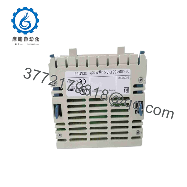
DDM163
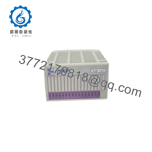
DDM163
Troubleshooting Quick Reference
| Symptom | Possible Cause | Relevance to This Part | Quick Check Method | Recommendation |
|---|---|---|---|---|
| No input or output LEDs illuminate | Missing DIAS power, failed upstream power module, loose DIAS connection, broken module bus, or failed DDM163 | ✅ Medium | Measure the DIAS supply at the adjacent power module and confirm the module is fully seated on the DIAS assembly. Inspect bus contacts and retention clips. | Check system power and bus seating before replacing DDM163. |
| One digital input remains off | Sensor has no 24 V DC supply, broken signal wire, failed proximity switch, wrong sensor type, poor common reference, or failed input channel | ✅ Medium | Measure sensor output and voltage at the corresponding input terminal. Compare the signal with a working input using the same sensor type. | Repair the sensor circuit first. Replace the card only if a verified 24 V input at the terminal is not detected. |
| Input LED is on but PLC program does not react | Incorrect I/O mapping, program interlock, wrong DIAS addressing, stale application download, or logic issue | ❌ Low | Monitor the physical input status in DIAS diagnostics and compare it with the PLC variable used in the application. | Troubleshoot software mapping and interlocks before replacing the I/O module. |
| One output does not energize | Output command absent, disabled output, blown protection, open field wire, failed relay/solenoid, bad output common, or damaged output channel | ✅ High | Command the output through an approved test procedure. Check the output LED, then measure voltage at the output terminal and across the field load. | Verify the load and field wiring. If the output LED/logic is active but no voltage appears at a known-good terminal and supply, the channel may have failed. |
| Output LED is on but valve or relay stays off | Open coil, failed relay interface, missing field common, blown downstream fuse, broken wire, or excessive voltage drop | ❌ Low | Measure voltage directly across the actuator coil while the output is on. With power isolated, measure coil resistance and inspect the fuse/interface relay. | Do not replace until the external actuator circuit passes inspection. |
| Several outputs fail together | Missing 24 V field supply, shared output-common break, group wiring issue, external fuse open, overload, or shorted field-device circuit | ✅ High | Use the wiring diagram to locate shared supply and return terminals. Measure 24 V DC at the module supply and compare with a working output group. | Investigate shared power and common wiring before changing the card. |
| Output voltage collapses when load is connected | Shorted load, excessive current demand, damaged cable, failing solenoid, insufficient 24 V supply, or output-stage damage | ✅ High | Disconnect the load under approved isolation. Test the output using a correctly rated resistive load or a verified relay interface. Measure supply voltage under normal load. | Correct the external overload before installing another module. |
| Repeated short-circuit indication or intermittent operation | Pinched cable, water ingress, wrong polarity, inductive kickback, overloaded output, loose terminal, or failed device | ✅ Medium | Isolate each field circuit one at a time. Inspect cable routes, terminal torque, and load current. Check for suppression across inductive loads. | Find the field fault first. Repeatedly resetting the output without removing the short can damage the replacement. |
| Module operates intermittently after cabinet work | Partially seated DIAS module, bent bus contact, loose terminal, disturbed 0 V reference, ESD damage, or wiring moved to the wrong point | ✅ Medium | Isolate power, reseat the , inspect connectors, and compare terminal numbering against pre-maintenance photos. | Reseat and re-terminate before replacing. A shifted wire on an 8-in/8-out module can imitate a hardware fault. |
❗ The outputs are positive-switching. SIGMATEK’s documentation identifies DDM 163 outputs as positive-switching 24 V DC outputs. Verify whether your load expects a sourcing/PNP output arrangement. Do not connect the module as though it were a sinking/NPN output card.
❗ Do not assume 2 A is available under every installation condition. The documentation lists 2 A for the outputs, but you must confirm the exact current-rating basis, output grouping, supply capacity, wiring size, ambient temperature, and duty cycle before connecting inductive loads or multiple solenoids.
❗ Use suppression on coils. Relays, solenoids, contactors, and pneumatic valves generate transients when switched off. Use the suppression component specified by the machine design. An unprotected coil can damage an output channel even if the DC current appears within rating.
❗ Take terminal photos before removal. I/O cards are often replaced during an outage under time pressure. Photograph the module, DIAS position, terminal numbers, wire labels, commons, fuses, and relay interfaces before you disconnect the old . It prevents the classic “new card is bad” mistake caused by one wire landed on the adjacent terminal.
If the fault remains unresolved, provide technical support with module-label photos, DIAS rack position, LED states, input/output terminal measurements, 24 V supply readings under load, field-device resistance, and controller diagnostics.
Frequently Asked Questions (FAQ)
What is SIGMATEK ?
SIGMATEK is a DIAS digital conversion module that combines eight digital inputs and eight digital outputs on one card. The module reads 24 V DC input signals and provides eight positive-switching 24 V DC outputs with short-circuit protection.
It is commonly used where a machine needs compact local I/O for sensors, limit switches, selector contacts, valves, relay interfaces, indicators, and other discrete 24 V DC devices.
What is the part number for ?
A commonly listed order number is 05-008-163. Another supplier listing references 05-006-163, which shows why procurement should be based on the actual side label rather than the name alone.
Request photos showing:
- or DDM 163 model marking
- Complete order number
- Hardware revision
- Serial number, if present
- DIAS bus/contact layout
- Terminal block and connector condition
Is an analog I/O module?
No. The official DDM 163 description identifies it as a digital module with eight 24 V DC inputs and eight positive-switching 24 V DC outputs. Do not rely on generic reseller descriptions that call it analog or a general controller. It is intended for discrete signals.
Are outputs sourcing or sinking?
The DDM 163 uses positive-switching outputs, which corresponds to a sourcing or PNP-style 24 V DC output arrangement. The module supplies positive voltage to the load when commanded on; the load normally returns to 0 V through the field wiring.
Before replacement, inspect the existing wiring and verify the required output topology. A PNP/sourcing output cannot directly replace an NPN/sinking output without changing the circuit design.
Can directly drive a solenoid valve?
It can switch compatible 24 V DC loads, but you must verify coil current, inrush current, duty cycle, output grouping, total module loading, and the module’s exact rating conditions first. The available documentation identifies 2 A outputs, but it does not by itself establish all application limits.
For critical valves, large solenoids, contactors, or loads with high inrush, use an appropriately rated interposing relay or interface module. Add the machine builder’s specified flyback diode, TVS, or other suppression device across DC coils.
Can I hot-swap the ?
Do not hot-swap it unless the DIAS system documentation and your site procedure explicitly permit it. Removing a live I/O module can interrupt outputs, generate inductive transients, cause unexpected actuator movement, and damage DIAS bus contacts.
Place the machine in a safe state, disable outputs, isolate 24 V DC field power where required, lock out the system, verify zero energy, then replace the module using ESD protection.
Why do the output LEDs work but field devices remain off?
An output LED confirms the controller is commanding that channel; it does not prove the load circuit is complete. Common root causes include:
- Missing 24 V DC field supply
- Open coil or failed solenoid
- Blown fuse in the actuator circuit
- Broken cable or loose terminal
- Missing 0 V return
- Failed interposing relay
- Excessive voltage drop under load
Measure voltage across the actual load while the output is commanded on. That test separates a module-command problem from a field-circuit problem quickly.
Is obsolete?
Treat as a legacy DIAS spare. It remains available through industrial automation surplus and repair channels, including listings for new, used, and refurbished material. For a production-critical DIAS machine, hold at least one verified spare and retain the system documentation, electrical drawings, and machine application backup.
What condition should I purchase?
For an I/O card, choose based on traceable condition and functional testing:
- New Original / New Surplus: Unused legacy inventory. Request actual photos of labels, housing, terminal block, connector contacts, packaging, and seals.
- Refurbished (tested): Previously used hardware inspected and tested. Request a channel-by-channel I/O report.
- Used, untested: Lowest confidence. Avoid for downtime-critical inventory unless you can test it in a DIAS fixture before an outage.
Do not accept vague phrases such as “good condition” or “pulled from a working machine” as a functional test.
What testing should a supplier perform before shipment?
For the exact being shipped, request a dated test record that includes:
- Label verification for , full order number, revision, and serial number where present
- Visual inspection for corrosion, damaged terminals, cracked casework, heat marks, altered labels, missing clips, and bent DIAS bus contacts
- DIAS bus power-up test in a compatible SIGMATEK fixture
- Status-LED and module-recognition verification
- Individual 24 V DC input test on all eight input channels
- Individual output-command and voltage test on all eight positive-switching outputs
- Controlled load test on each output using an appropriate resistive or relay-interface load
- Short-circuit-protection verification only where the test procedure and equipment safely support it
- Sustained operation with thermal observation
- ESD-safe packaging, QC sign-off, and test video or photos upon request
For , “powers on” is not enough. The supplier should verify all 8 inputs and 8 outputs.



