
 WhatsApp: +86 16626708626
 Email:
  Phone: +86 16626708626
Description
Key Technical Specifications
| Parameter | Value |
|---|---|
| Model | DNC115 / DNC 115 |
| Manufacturer | SIGMATEK |
| Article Number | 05-011-115 |
| System | DIAS Bus |
| Module Type | 1-axis positioning module |
| Encoder Channels | 1 |
| Encoder Signals | A, /A, B, /B, R, /R |
| Encoder Interface | RS-422, 150 Ω termination |
| Maximum Input Frequency | 125 kHz |
| Maximum Counter Frequency | 500 kHz |
| Counting Method | 4× evaluation |
| Counter Resolution | 16 bit |
| Encoder Supply | +5 V / 0.6 A, short-circuit protected |
| Digital Inputs | 3 |
| Digital Input Voltage | +24 V typical, +30 V maximum |
| Digital Input Current | 5 mA at +24 V |
| Digital Input Delay | 0.1 ms typical |
| Analog Output | 1 channel, -10 to +10 VDC |
| Analog Resolution | 12 bit / 5 mV per bit |
| Analog Accuracy | 0.4% of output magnitude |
| Analog Settling Time | <50 µs |
| Optocoupler Outputs | 2, potential-free |
| Output Voltage | +30 VDC maximum |
| Output Current | 100 mA maximum |
| Supply Voltage | 18–30 VDC |
| Module Consumption | <200 mA, including encoder supply |
| DIAS Bus Current | 50 mA typical / 80 mA maximum |
| Required Terminal Module | DKL 032, Article No. 05-024-032 |
| Connection | 17-pole, 3-row spring terminal strip |
| Operating Temperature | 0 to +60 °C |
| Storage Temperature | -20 to +85 °C |
| Humidity | 0–95%, non-condensing |
| Protection Rating | IP20 |
| Dimensions | Approximately 98 × 80 × 93 mm |
The official SIGMATEK documentation identifies the DNC 115 as a one-axis positioning module, not a general-purpose Ethernet controller or 16-channel digital-output module. It accepts incremental encoder signals at RS-422 levels, performs 4× counting, and provides a 12-bit analog setpoint output.
The module has three 24 VDC digital inputs for reference/limit functions and two potential-free optocoupler outputs. The official specification gives a maximum encoder input frequency of 125 kHz and a maximum counter frequency of 500 kHz.
Product Introduction
The SIGMATEK DNC115 is a one-axis positioning module for the DIAS bus system. It processes differential incremental encoder feedback through an RS-422 interface and provides a 16-bit position counter, three 24 VDC digital inputs, two isolated optocoupler outputs, and a 12-bit ±10 V analog command output for interfacing with a motor controller or frequency converter.
The module is intended for closed-loop axis positioning where encoder feedback and an analog motion command must be handled within the SIGMATEK DIAS architecture. Its 500 kHz maximum counter frequency, sub-50 µs analog settling time, hardware latch functions, and interrupt capability on input 3 support time-sensitive positioning and reference operations.
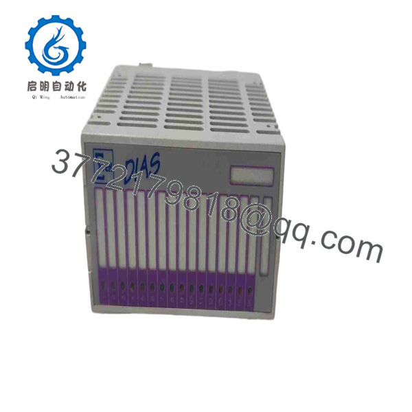
DNC115
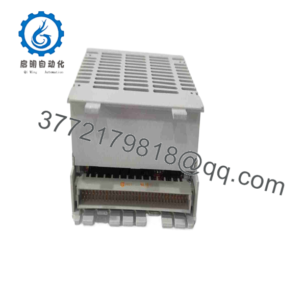
DNC115
Installation & Configuration Guide
Stage 1 — Pre-Installation Preparation
- Confirm the module marking DNC115 / DNC 115 and article number 05-011-115.
- Verify that the existing control system is a SIGMATEK DIAS installation.
- Confirm the required DKL 032 terminal module, which is specified by SIGMATEK for the DNC 115.
- Back up the DIAS configuration, application program, positioning parameters, scaling values, and axis-related software settings.
- Record encoder wiring, reference-switch wiring, limit inputs, analog command wiring, and Q1/Q2 output usage.
- Isolate the machine power and follow the site’s lockout/tagout procedure.
- Prepare an ESD wrist strap, multimeter, insulated tools, and suitable shielded signal cables.
- Confirm that the encoder uses compatible RS-422 A/A̅, B/B̅, and R/R̅ signals.
Stage 2 — Removing the Old Module
- Power down the control cabinet and verify absence of hazardous voltage.
- Record the module position and DIAS bus arrangement.
- Disconnect the 17-pole terminal connection from the DKL 032 terminal module.
- Label the encoder, +24 VDC, analog, input, and optocoupler output wiring.
- Remove the DNC115 from the DIAS installation according to the applicable rack/module procedure.
- Inspect the terminal module, connector contacts, wiring, and DIN-rail grounding.
- Check encoder cable shielding and routing before installing the replacement.
Stage 3 — Installing the DNC115
- Verify the replacement article number and hardware version.
- Install the module in the correct DIAS bus position.
- Confirm mechanical coding before seating the module.
- Connect the DKL 032 terminal module and its 17-pole spring terminal interface.
- Wire encoder signals A, /A, B, /B, R, and /R according to the SIGMATEK connection diagram.
- Connect the encoder’s +5 V supply only after confirming the encoder’s current requirement.
- Connect the three 24 VDC inputs for reference and end-position monitoring.
- Connect the ±10 V analog output to the compatible motor controller or drive input.
- Connect Q1/Q2 only to loads within the specified +30 VDC / 100 mA maximum output rating.
- Keep analog wiring short and separated from digital signal wiring; SIGMATEK specifies shielded signal wiring and connection of the shielding to a common shield rail.
Stage 4 — Power-On & Testing
- Verify the 18–30 VDC supply and polarity before energizing the module.
- Check the DIAS bus supply and module seating.
- Confirm the +5 V encoder supply status LED.
- Rotate the encoder manually or under controlled low-speed operation and verify A/B quadrature counting.
- Confirm the reference pulse and input status.
- Check the three digital inputs individually.
- Verify the analog output at 0 V before applying positive or negative command values.
- Confirm the analog output scaling against the motor controller input.
- Test Q1 and Q2 with an appropriate load without exceeding the 100 mA output rating.
- Verify latch and interrupt behavior where used by the application.
- Run a low-speed axis test and confirm that commanded direction, encoder direction, reference operation, and end limits agree with the machine configuration.
- Only return the axis to automatic operation after the complete motion chain has passed the dry-run test.
Frequently Asked Questions
Q1. What is the SIGMATEK DNC115?
The is a one-axis positioning module for the SIGMATEK DIAS bus system. It accepts an incremental encoder through an RS-422 interface and provides analog and digital interfaces for axis control.
Q2. Is a 16-channel digital output module?
No. Some secondary-market listings incorrectly describe DNC-115 as a 16-channel digital-output module. The official SIGMATEK DNC 115 documentation identifies it as a one-axis positioning module with one encoder channel, three digital inputs, one analog output, and two optocoupler outputs.
Q3. What encoder signals does the accept?
It accepts incremental encoder A, /A, B, /B, R, and /R signals at RS-422 levels, with a specified 150 Ω load. Maximum input frequency is 125 kHz and maximum counter frequency is 500 kHz using 4× evaluation.
Q4. What is the analog output range?
The module provides one -10 to +10 VDC analog output with 12-bit resolution, equivalent to approximately 5 mV per bit. The specified analog accuracy is 0.4% of output magnitude and settling time is less than 50 µs.
Q5. What terminal module does require?
SIGMATEK specifies the DKL 032 terminal module, Article No. 05-024-032. The signal connection uses a 17-pole, three-row spring terminal arrangement.
Q6. What supply voltage does the require?
The external supply specification is 18–30 VDC, with module consumption below 200 mA including the encoder supply. The DIAS bus also supplies +5 V, with typical bus current of 50 mA and a maximum of 80 mA.
Q7. Can I directly replace a with another module described as ?
Verify the article number 05-011-115, hardware version, terminal module, DIAS configuration, and application software before substitution. This is particularly important because secondary-market databases contain conflicting descriptions of the . The official SIGMATEK documentation should take precedence when determining the module’s function and electrical specifications.



