WhatsApp: +86 16626708626
 Email:
 Phone: +86 16626708626
Description
Core Product Summary (Brand / Model / Key Attributes)
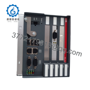
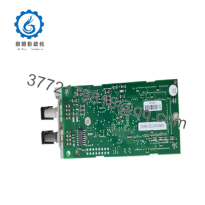
The SIS PM01-PM01-A-V001 is a specialized process management and safety control module engineered for deployment within industrial automation and Safety Instrumented System (SIS) architectures. Operating as a critical core unit, it provides robust monitoring, signal processing, and integrated communication capabilities designed to maintain high reliability and functional safety across complex industrial processes.
The module incorporates multi-channel input and output handling, supporting isolated digital inputs and configurable relay outputs to manage safety-related signals from field sensors and devices. Built for harsh operational environments, the unit features a wide operating temperature range, standard 24 V DC power supply compatibility with redundant options, and support for standard industrial communication protocols such as RS-485 and Modbus.
Key Technical Specifications
| Parameter | Verified Specification |
|---|---|
| Model / Order Number | SIS PM01-PM01-A-V001 (also designated as SIS PM01) |
| Product Type | Process Management / Safety Control Module |
| Input Channels | 16 isolated digital inputs |
| Output Channels | 8 configurable relay outputs |
| Communication Protocols | RS-485 / Modbus (optional Ethernet TCP/IP support) |
| Power Supply Requirements | 24 V DC (supports redundant power configurations) |
| Power Consumption | ≤12 W |
| Processor & Memory | Embedded 32-bit microcontroller with 128 MB Flash and 64 MB SDRAM |
| Operating Temperature Range | −20∘C to +65∘C |
| Mounting Type | DIN rail or panel mounting |
| Safety Compliance | IEC 61508 SIL2 / SIL3 compatible application design |
Detailed Product Overview
Within safety-critical industrial environments such as oil and gas, power generation, and heavy chemical processing, Safety Instrumented Systems (SIS) require deterministic hardware to execute emergency shutdown and process monitoring functions. The SIS PM01-PM01-A-V001 module serves as a process management processor designed to capture critical field data, evaluate process safety limits, and drive reliable control or trip actions.
The module processes incoming signals from safety sensors and switches, executing real-time logic evaluation via an onboard 32-bit microcontroller architecture. Built-in diagnostics continuously monitor channel health, internal memory integrity, communication link status, and power supply voltages. Its ruggedized physical construction and compliance standards help ensure reliable operation under continuous vibration and thermal stress typical of industrial control rooms and marshalling cabinets.
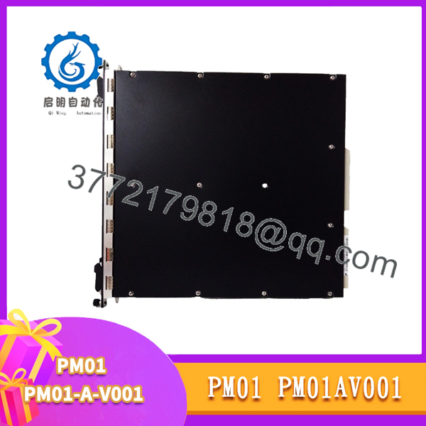
PM01-PM01-A-V001
Engineering Selection Highlights
- Safety System Architecture Fit: Designed for integration into safety-critical instrumentation loops → Verify that the loop safety integrity level (SIL rating) matches plant requirements before deployment.
- I/O Configuration Match: Features 16 isolated digital inputs and 8 configurable relay outputs → Check field sensor and actuator load requirements against the module’s channel capacity.
- Communication Interfacing: Supports RS-485 / Modbus protocols for upstream data transfer → Confirm network compatibility with existing supervisory control and data acquisition (SCADA) or DCS architectures.
- Power and Redundancy: Operates on a standard 24 V DC supply with redundant power input provisions → Ensure cabinet power distribution supplies stable, backed-up voltage rails.
System Compatibility & Integration Requirements
| Item / Dependency | Verified Compatibility or Requirement | Practical Note |
|---|---|---|
| Control System Framework | Safety Instrumented Systems (SIS) Architecture | Designed to operate within dedicated safety control networks or standalone automation nodes. |
| Power Supply | 24 V DC Nominal | Provision for redundant power feeds to maintain high availability in safety loops. |
| Field Wiring | Shielded twisted-pair cables for RS-485; isolated signal lines for I/O | Proper grounding and shielding are required to prevent electromagnetic interference (EMI) in industrial settings. |
| Mounting Hardware | Standard DIN rail or secure panel mount | Allow adequate spacing around the module for thermal dissipation and wire routing. |
Dimensions, Mounting & Connection Notes
- Physical Dimensions: Approximately 175 mm×120 mm×40 mm175 mm \times 120 mm \times 40 mm175 mm×120 mm×40 mm (W×H×DW \times H \times DW×H×D).
- Approximate Weight: 0.65 kg0.65 kg0.65 kg.
- Mounting Options: Designed for standard DIN rail or direct panel mounting inside industrial control cabinets.
- Connection Interface: Features clearly labeled terminal blocks for power input, digital inputs, relay outputs, and communication lines. Standard ESD-safe handling and power-off isolation must be observed during wiring or hardware replacement.
FAQ
What is the SIS PM01-PM01-A-V001? It is a process management and safety control module utilized in industrial Safety Instrumented Systems (SIS) to handle signal processing, monitoring, and I/O control.
What are the primary I/O capacities of this module?The module features 16 isolated digital inputs and 8 configurable relay outputs.
What communication protocols does it support?It communicates via RS-485 using Modbus protocols, with options for Ethernet TCP/IP integration depending on system configuration.
What power supply does the module require?It operates on a 24 V DC power supply and supports redundant power configurations.
What safety standards are associated with its application environment?It is designed for use in applications requiring compliance up to IEC 61508 SIL2 / SIL3 standards.
Verification & Troubleshooting Notes
- Diagnostic LED Check: Inspect the module’s front-panel status indicators to confirm power status, CPU health, communication traffic, and channel-level errors.
- Power Supply Verification: Use a digital multimeter to verify that the 24 V DC input voltage is stable and within tolerance at the terminal block before troubleshooting internal logic faults.
- Wiring and Termination Inspection: Check all field wiring terminations for looseness, corrosion, or ground loops that could induce false digital input states or intermittent communication drops.
- Safe Maintenance Protocol: Always follow facility lockout/tagout (LOTO) and safety instrumented function bypass procedures before disconnecting safety-related I/O wiring or swapping modules.