
 WhatsApp: +86 16626708626
 Email:
  Phone: +86 16626708626
Description
Key Technical Specifications
| Parameter | Specification |
|---|---|
| Manufacturer | SMC Corporation |
| Model | EX120-SPR1-B |
| Alternative Reference | EX120SPR1B |
| Product Type | PROFIBUS-DP SI / serial interface unit |
| Housing Type | EX120 |
| Primary Application | SMC pneumatic valve manifold control |
| PROFIBUS Mode | DP Slave |
| PROFIBUS Standard | IEC 61158 / EN 50170 |
| Physical Layer | RS-485 |
| Baud Rate | 9.6 kbit/s to 12 Mbit/s |
| Baud Rate Detection | Automatic |
| Maximum Outputs | 16 |
| Maximum Valve Coils | 16 single-solenoid coils / 8 double-solenoid valves |
| Output Voltage | +24 V DC ±10% |
| Output Power | 2.1 W maximum per output |
| Output Polarity | Minus Common |
| Output Protection | One micro-fuse per byte |
| Electronics Supply | +24 V DC ±10% |
| Electronics Current | 70 mA maximum without load |
| Valve Load Current | 1.4 A maximum |
| Supply Connector | 5-pole round connector, DIN 45322 |
| PROFIBUS Connector | 9-pin D-Sub |
| Addressing | Rotary-switch hardware or software addressing |
| Hardware Address Range | 02–99 |
| Software Address Range | 02–126 |
| Default Address | 03 |
| GSD Files | SMCB1401.GSD / SMCB1400.GSD depending on addressing mode |
| Operating Temperature | 0 to +50 °C |
| Storage Temperature | –20 to +85 °C |
| Relative Humidity | 10–95%, non-condensing |
| Enclosure Rating | IP20 |
| Galvanic Isolation | 50 Veff rated / 500 Veff surge |
| CE | Yes |
| Diagnostics | RUN, DIA, BF LEDs |
The SMC instruction manual identifies EX120-SPR1-B as a PROFIBUS-DP SI unit with 16 output drivers and compatibility with SMC VQ1000/VQ2000 valve series. The EX120 housing uses direct mounting without a ribbon cable and is distinct from EX121/EX122 mounting arrangements.
The unit automatically detects PROFIBUS-DP transmission speed from 9.6 kbit/s through 12 Mbit/s. At 12 Mbit/s, the documented maximum cable length for PROFIBUS cable Type A is 100 m; at 1.5 Mbit/s it is 200 m, and at 93.75 kbit/s it reaches 1,200 m.
Product Introduction
The SMC EX120-SPR1-B is a PROFIBUS-DP slave interface for controlling SMC pneumatic valve manifolds. It provides 16 output drivers and can operate up to 16 single-solenoid coils or 8 double-solenoid valves. The EX120 version is intended for SMC VQ1000/VQ2000 valve configurations.
The unit uses a 24 V DC supply, 9-pin D-Sub PROFIBUS connection, automatic baud-rate detection, rotary-switch station addressing, and front diagnostics LEDs. Its electronics and valve-load supplies are separately provided through the 5-pole power connector, which is important when diagnosing valve power faults.
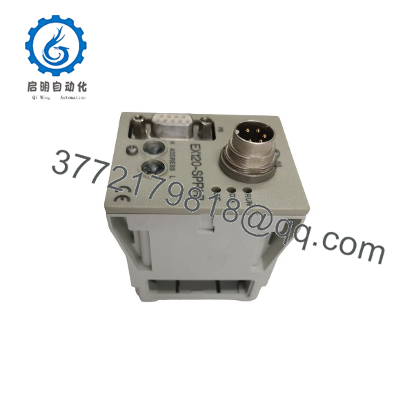
EX120-SPR1-B
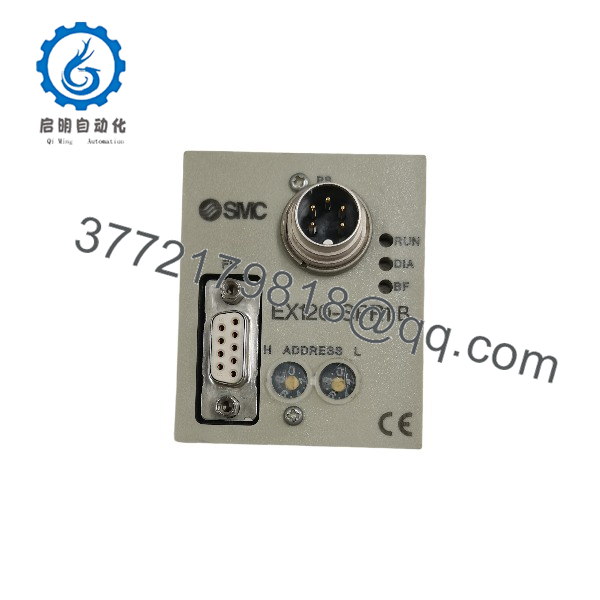
EX120-SPR1-B
Installation & Configuration Guide
Stage 1 — Pre-Installation | ~5 minutes
- Switch off the system supply before disconnecting the EX120-SPR1-B. SMC specifies that installation and wiring must be performed with supply voltage switched off.
- Record the existing PROFIBUS station address and inspect the two rotary switches.
- Record whether the internal address-mode selector is configured for hardware addressing or software addressing.
- Confirm that the installed valve manifold is an appropriate configuration using the VQ1000/VQ2000 family.
- Back up the PLC PROFIBUS configuration and confirm the correct GSD file.
- Check the 24 V DC supply. The permitted range is 21.6–26.4 V DC.
- Confirm that the PROFIBUS cable is shielded twisted pair and that the network topology has proper termination.
⚠️ Do not change the GSD file simply because another EX12x module is being installed. The manual specifies different GSD files for hardware and software addressing.
Stage 2 — Remove the Existing Module | ~5 minutes
- Isolate the 24 V DC supply.
- Disconnect the 5-pole power connector.
- Disconnect the 9-pin PROFIBUS connector.
- Disconnect the SI unit from the valve manifold as required by the physical installation.
- Inspect the connector and valve-manifold interface for bent contacts, contamination, or mechanical damage.
- Record the original address-switch positions before removing the unit.
Stage 3 — Install -SPR1-B | ~10 minutes
- Install the replacement SI unit in the same mounting position.
- Match the original station-address configuration.
- If hardware addressing is used, set the rotary switches to the required decimal address. The documented hardware range is 02–99, with 03 as the factory default.
- If software addressing is used, verify the internal selector position and use the corresponding GSD file.
- Connect the valve manifold interface.
- Connect the 5-pole power connector.
- Connect the 9-pin PROFIBUS cable.
- Do not reverse PROFIBUS A/B signal conductors. The manual identifies pin 3 as RxD/TxD-P and pin 8 as RxD/TxD-N.
- Verify PROFIBUS termination at the two physical ends of the network.
⚠️ The -SPR1-B has separate electronics and valve-load power connections. A normal RUN indication does not by itself prove that the solenoid-valve supply is correct.
Stage 4 — Power-On & Commissioning | ~10 minutes
- Apply 24 V DC within the specified 21.6–26.4 V range.
- Check the green RUN LED.
- Check the red BF LED for PROFIBUS communication faults.
- Check the red DIA LED for valve-control or valve-supply faults.
- Confirm that the PLC recognizes the PROFIBUS slave at the expected station address.
- Verify the correct GSD configuration in the PROFIBUS master.
- Test each configured valve output individually.
- Confirm that the output mapping corresponds to the actual valve-coil arrangement.
- For VQ manifolds, verify that the valve coil arrangement matches the configured bit allocation.
The assigns output drivers as bits 0–15. A typical eight-station double-solenoid configuration uses two bits per station, while a 16-station single-solenoid configuration uses bits 0–15.
⚠️ If BF remains illuminated, check the PROFIBUS address, GSD file, termination, cable polarity, and master configuration before replacing the SI unit. If DIA is illuminated, check the valve supply voltage and coil load separately.
FAQ
1. What dhe SMC do?
It is a PROFIBUS-DP slave SI unit used to control SMC pneumatic solenoid valves. It provides 16 output drivers for a valve manifold.
2. How manyes can control?
It can control a maximum of 16 single-solenoid coils or 8 double-solenoid valves, provided the total number of coils does not exceed 16. It does not provide sensor inputs.
3. Which SMC valves are compe with ?
The SMC manual specifically identifies VQ1000 and VQ2000 valve seror the . EX121/EX122 configurations are associated with different SMC valve families and mounting arrangements.
4. What GSe does use?
It depends on the addressing method. SMCB1401.GSD is used for hardware addressing through the rotary switches; SMCB1400.GSD is used for software addressing through the PROFIBUS protocol.
5. What is the normal station address?
The factory default is documented as 03 with hardware addressing enabled. Hardware addressing supports 02–99. Software addressing supports 02–126. A PROFIBUS address must be unique on the network.
6. Is obsolete?
Current aftermarket sources identify the part as discontinued by the manufacturer, while SMC-related product indexes still list the model. For a plant replacement, treat it as a legacy part and verify whether the offered unit is new old stock, used, or refurbished.
7. What should be checked before buying a replacement?
For an exact replacement, verify the suffix, PROFIBUS interface, housing type, valve manifold compatibility, station-address configuration, GSD file, output arrangement, and physical condition. Do not substitute EX121-SPR1-B or EX122- solely because the electronics are related; the SMC manual specifies different mounting and valve-family arrangements for those housings.



