 WhatsApp: +86 16626708626
 Email:
 Phone: +86 16626708626
Description
Core Product Summary (Brand / Model / Key Attributes)
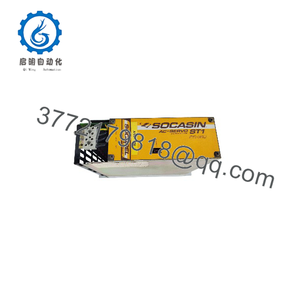
The SOCAPEL ST1/25-310 is a digital AC motion controller and power servo drive unit within the SOCASIN ST1 system family. Engineered for high-precision industrial automation, this compact drive module manages three-phase AC synchronous (DC brushless) and asynchronous (induction) motors across multi-axis machinery setups.
The drive operates from a nominal 310 VDC power bus supplied by a central BA4 series supply unit, alongside an auxiliary 48 VDC logic power input. Capable of delivering up to 18 A RMS continuous output current at a 9.8 kHz switching frequency, the ST1/25-310 supports closed-loop position, velocity, and current control with high bandwidth response. It incorporates resolver-based feedback processing, integrated status diagnostics, and standard RS-485 serial communication for parameterization and system integration.
Key Technical Specifications
| Parameter | Specification |
| Product Type | Digital AC Servo Drive / Motion Controller |
| Product Family | SOCAPEL SOCASIN ST1 Series |
| OEM Part Number | 024.7751.B |
| Nominal DC Bus Voltage | 310 VDC (supported up to 360 VDC max) |
| Auxiliary Control Voltage | 48 VDC |
| Maximum Continuous Output Current | 18 A RMS |
| PWM Switching Frequency | 9.8 kHz |
| Supported Motor Types | Three-phase AC synchronous (brushless DC) and induction motors |
| Position Resolution | 25,736 increments per resolver revolution |
| Position Measurement Accuracy | ±2.5 arc min (1/8500 revolution, excluding resolver error) |
| Speed Range | 0 to 22,500 rpm |
| Cycle Time | 0.33 ms |
| Velocity Signal Bandwidth | Up to 600 Hz |
| Current Loop Bandwidth | > 1000 Hz |
| Operating Temperature | 0 °C to +50 °C (+32 °F to +122 °F) |
Detailed Product Overview
The SOCAPEL ST1/25-310 operates as a slave drive unit within a modular multi-axis motion architecture. Rather than converting AC line power individually at each axis, the ST1 power stage draws a direct 310 VDC supply from a centralized BA4 power supply module, minimizing overall panel footprint and optimizing power distribution across multi-drive configurations.
Equipped with an internal microprocessor, the unit executes high-speed digital control loops. The current loop operates at a bandwidth exceeding 1000 Hz, while the velocity loop handles bandwidths up to 600 Hz with a rapid 0.33 ms cycle time. This dynamic response enables precise speed regulation up to 22,500 rpm and high-resolution positioning via standard resolver feedback.
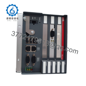
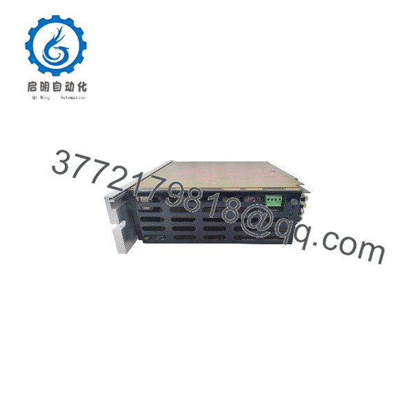
Physical layout features top and bottom power terminal connections for the shared DC bus and motor leads, front-panel control terminals for I/O and feedback connections, and diagnostic indicators for monitoring operational state and fault status.
Engineering Selection Highlights
- Shared DC Bus Architecture: Integrates with BA4 DC bus power units (310 VDC nominal) to streamline multi-axis panel wiring and footprint.
- Dynamic Servo Control: Fast 0.33 ms update loop and high bandwidths (>1000 Hz current, up to 600 Hz velocity) deliver accurate motion trajectories.
- Versatile Motor Compatibility: Controls both 3-phase AC synchronous PM brushless motors and induction motors.
- High-Precision Resolver Feedback: Provides high positioning resolution (25,736 increments per revolution) without fragile optical disks.
- Auxiliary Isolation: Features a dedicated 48 VDC auxiliary supply line to maintain control logic power independently of the main high-voltage DC bus.
ST1 25-310
ST1 25-310
System Compatibility & Integration Requirements
| Item / Dependency | Verified Compatibility or Requirement | Practical Note |
| Main DC Power Supply | SOCAPEL BA4 Series Supply Unit (BA4/30-50 or BA4/60-80) | Supplies the nominal 310 VDC high-voltage bus line |
| Logic Power Supply | 48 VDC Auxiliary Supply | Powers drive control electronics independently |
| Feedback Sensor | Standard Industrial Resolver | Required for high-precision motor position and velocity feedback |
| Protection Accessories | IP20 Bottom Protection Set (P/N 024.7820) | Recommended at unit bases to prevent contact with exposed 310 VDC terminals |
Dimensions, Mounting & Connection Notes
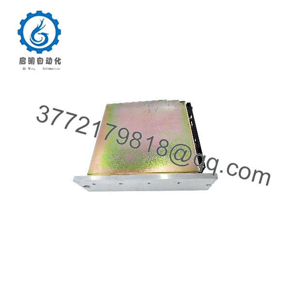
- Mounting Configuration: Direct cabinet panel mounting via backplate heat-sink assembly.
- Power Connections: Heavy-duty screw terminals for DC bus input (310 VDC) and motor phase output lines.
- DC Bus Distance: The extended DC bus connections between the supply unit and drive modules should not exceed 1 meter (or 2 meters if the supply unit is centrally positioned).
- Grounding Practice: Ensure the negative rail of the DC bus (0V) is tied securely to local chassis ground using the provided grounding strap.
- Safety Clearance: Maintain adequate vertical clearance above and below the drive module to allow natural convection or forced-air cooling through the heatsink fins.
FAQ
- What is the SOCAPEL ST1/25-310?
It is a digital AC servo drive unit designed for three-phase AC synchronous and asynchronous motor control in industrial motion applications.
- What is the main bus voltage requirement for the ST1/25-310?
The module operates on a nominal 310 VDC bus voltage (rated up to 360 VDC max) supplied by a companion BA4 power supply unit.
- What is the maximum output current rating for this model?
The ST1/25-310 provides up to 18 A RMS maximum output current.
- What feedback device is utilized by the ST1/25-310 drive?
It uses resolver feedback to achieve position resolution up to 25,736 increments per revolution.
- What auxiliary voltage is required for the drive logic?
The control logic requires a dedicated 48 VDC auxiliary power supply.
Verification & Troubleshooting Notes
- DC Bus Voltage Checking: Before servicing or handling wiring, verify that the 310 VDC bus has completely discharged using an appropriately rated voltmeter.
- Bus Protection Shielding: Ensure the lower terminal IP20 protection covers are installed to shield operator exposure to live 310 VDC terminals.
- Resolver Phase Alignment: Check resolver wiring and phase orientation if position errors or unexpected motor runaway conditions occur during commissioning.
- DC Bus Cable Length Limits: Ensure high-voltage DC bus interconnecting straps stay within the maximum specified length (1 to 2 meters) to avoid excessive voltage drops or noise coupling.