
 WhatsApp: +86 16626708626
 Email:
  Phone: +86 16626708626
Description
Key Technical Specifications
| Parameter | Value |
|---|---|
| Manufacturer | H.M. Stein Sohn GmbH |
| Model | F404002A |
| Module Designation | VBI6 |
| Product Type | VISTA Bus Interface Module |
| System Platform | Stein Sohn VISTA Automation |
| Main Function | Internal VISTA bus communication interface |
| Supply Voltage | 24 VDC |
| Hardware Revision | Verify by unit label (Rev. A / Rev. C variants reported) |
| Marking Reference | E710.1 (reported on some units) |
| Communication Interface | VISTA proprietary bus interface |
| Installation Type | Industrial control cabinet / VISTA rack mounting |
| Application Area | Marine automation, vessel monitoring, industrial control |
| Approximate Weight | 620 g (specific referenced assembly) |
| Lifecycle Status | Legacy / discontinued spare part |
| Condition Options | New Original, New Surplus, Refurbished (tested) |
Product Introduction
The Stein Sohn F404002A is a VBI6 VISTA Bus Interface Module used in Stein Sohn VISTA Automation systems. It provides the communication interface between VISTA system components and the internal automation bus architecture. The module is mainly found in legacy marine and industrial control installations where the original VISTA platform remains in operation.
The F404002A is not a general-purpose PLC communication card. Replacement decisions depend on the installed VISTA configuration, hardware revision, connector arrangement, and bus architecture. Verify the exact module revision before installation to avoid communication faults after replacement.
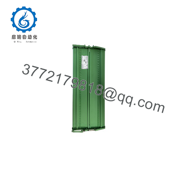
F404002A
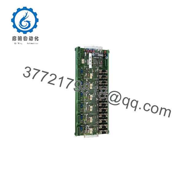
F404002A
Installation & Configuration Guide
Stage 1: Pre-Installation Preparation (Approx. 15 minutes)
⚠️ Safety First
- Notify operations before removing the Stein Sohn F404002A module.
- Confirm the vessel or industrial process is in an approved maintenance state.
- Apply lockout/tagout procedures to the control cabinet power supply.
- Wait at least 5 minutes for stored electrical energy discharge.
- Verify zero voltage with a calibrated multimeter.
Tools Required
- ESD wrist strap
- PH1 screwdriver
- Digital multimeter
- Wire labels
- Smartphone for photos
- VISTA Automation system documentation
Data Backup
Before removing the module:
- Record:
- Module model number
- Hardware revision
- Slot position
- Connector arrangement
- Photograph:
- Front label
- PCB identification markings
- Bus wiring
- LED indicators
- Rack position
- Document:
- VISTA bus connections
- Connected modules
- Power supply wiring
Stage 2: Removing the Old Module (Approx. 10 minutes)
- Remove cabinet access covers if required.
- Label all VISTA bus wiring.
- Disconnect communication connectors carefully.
- Release mounting clips or retaining screws.
- Pull the F404002A straight out from the rack.
Inspect:
- Backplane contacts
- Connector pins
- PCB condition
- Signs of corrosion or moisture damage
⚠️ Note: Keep the original F404002A until the replacement module completes communication testing. The old unit is the best reference for revision matching.
Stage 3: Installing the New Module (Approx. 15 minutes)
- Wear an ESD strap before handling the replacement module.
- Verify:
- Model: Stein Sohn
- Module: VBI6
- System: VISTA Automation
⚠️ Configuration Clone — Critical Step
- Match the original installation:
- Hardware revision
- Connector layout
- Bus wiring
- Module position
- Address settings if applicable
- Insert the module into the correct rack position.
- Ensure the connector is fully seated.
- Secure the retaining hardware.
- Reconnect all communication wiring.
Self-Checklist
- Correct verified
- VBI6 designation confirmed
- Revision checked
- Bus wiring matched
- Module secured properly
Stage 4: Power-On & Testing (Approx. 20 minutes)
Pre-Power Check
- Verify 24 VDC supply polarity.
- Check for wiring shorts.
- Confirm bus cable continuity.
- Verify connector seating.
Power-On Steps
- Energize the VISTA control cabinet.
- Observe module status indicators.
- Verify the VISTA bus initializes correctly.
- Check communication between connected modules.
- Monitor for bus errors or communication interruptions.
⚠️ Troubleshooting Note
- No communication: Check bus wiring, module revision, and connector seating.
- Intermittent communication: Inspect shielding, grounding, and aging connectors.
- Startup failure: Verify 24 VDC supply stability and module compatibility.
Frequently Asked Questions (FAQ)
Can the Stein Sohn be hot-swapped under power?
No. The is part of the VISTA Automation communication architecture. Removing the module while energized can interrupt bus communication and affect connected automation functions. Power isolation is recommended before replacement.
What is the main function of the ?
The functions as the VBI6 VISTA Bus Interface Module. It provides communication between VISTA system components through the proprietary VISTA bus architecture.
Is the Stein Sohn obsolete?
Yes. The is a legacy VISTA Automation component. Industrial suppliers list the module as discontinued by the manufacturer, so existing users typically maintain spare inventory or use tested replacement units.
Can another VISTA module replace the ?
Not automatically. The replacement must match the VBI6 function, hardware revision, connector design, and installed VISTA system configuration. A physically similar module may not communicate correctly.
Will replacing the erase the control program?
No. The is a communication interface module, not the main application controller. However, incorrect bus configuration can prevent system communication after replacement.
Why is the price different between suppliers?
Legacy automation modules are commonly available as New Original stock, New Surplus inventory, or Refurbished (tested) units. Pricing depends on condition, revision availability, testing documentation, and warranty coverage.
What should I verify before ordering a Stein Sohn ?
Check:
- Exact model:
- Module type:
- VISTA Automation compatibility
- Hardware revision
- Connector arrangement
- Existing bus configuration
- Supply voltage requirement
How should a surplus be tested before installation?
A proper inspection process should include:
- Verify OEM label and serial number.
- Confirm identification.
- Inspect PCB and connectors.
- Test on a compatible Stein Sohn VISTA system.
- Verify 24 VDC operation.
- Confirm stable bus communication.
- Generate a functional test report.
Test photos and records should be retained for maintenance traceability.



