
 WhatsApp: +86 16626708626
 Email:
  Phone: +86 16626708626
Description
Key Technical Specifications
| Parameter | Value |
|---|---|
| Manufacturer | SUPCON |
| Model | FW252-04A |
| Product Type | DCS Power Supply Module |
| System | ECS-100 |
| Power Cage | FW253 |
| Output Voltage | 24 VDC |
| Rated Output Power | 150 W |
| Output Current | Approximately 6.25 A at 24 VDC; some market listings state 6.5 A |
| Input Voltage | 220 VAC reported by industrial listings; verify nameplate before installation |
| Application | ECS-100 DCS control-system power |
| Installation | FW253 power cage |
| Related Module | FW252-03A — 5 V, 75 W version |
| Related Module | FW252-05 — 5 V / 24 V, 110 W version |
| Lifecycle | Legacy ECS-100 component |
SUPCON’s ECS-100 system documentation identifies FW252-04A as a 24 V, 150 W power supply installed in the FW253 power cage. The same documentation identifies FW252-03A as the 5 V, 75 W variant and FW252-05 as the 5 V/24 V, 110 W variant.
A separate industrial equipment listing reports 220 VAC input, 24 VDC output, and 6.5 A capacity for -04A. Because 24 V × 6.5 A equals 156 W, while SUPCON’s ECS-100 documentation specifies 150 W, I would use 150 W as the documented system rating and verify the actual nameplate before calculating maximum loading.
Product Introduction
The SUPCON FW252-04A is a 24 VDC, 150 W power supply module for the ECS-100 DCS, installed in the FW253 power cage. It provides the 24 V supply required by the applicable control-system hardware.
This module is primarily a maintenance replacement for existing installations. It should not be substituted with -03A or -05 simply because those modules share the family designation; their output configurations are different.
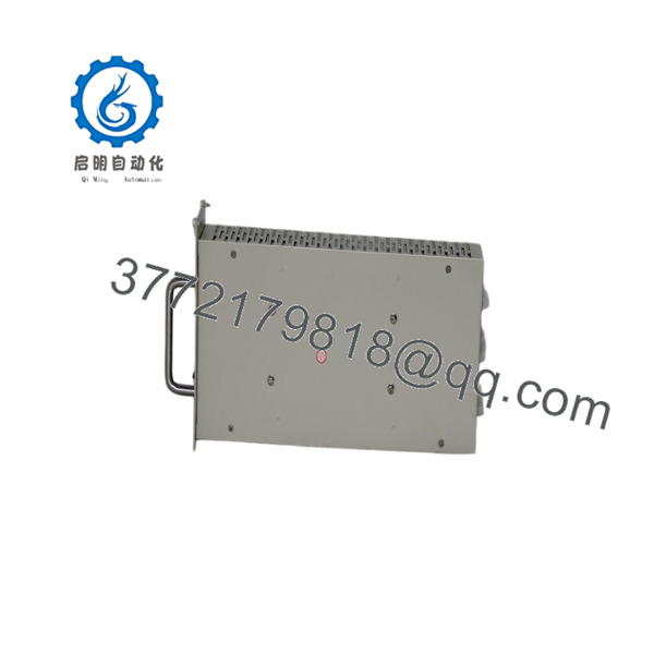
FW252-04A
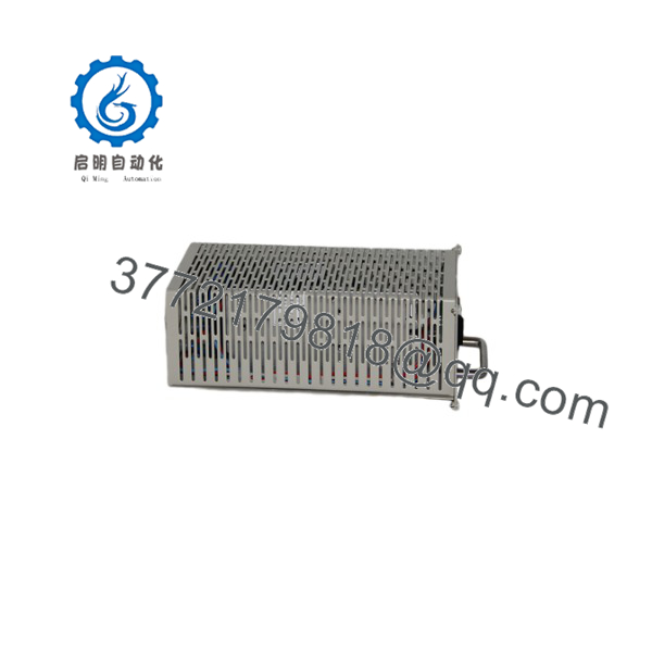
FW252-04A
Installation & Configuration Guide
Stage 1: Pre-Installation Preparation — Approximately 10 Minutes
⚠️ Safety First
- Notify operations and obtain an approved DCS maintenance window.
- Place the controlled process in its approved safe state.
- Apply lockout/tagout (LOTO) to the applicable power source.
- Wait at least 5 minutes for stored energy to dissipate.
- Verify the relevant supply is de-energized with a properly rated multimeter.
Tools Required
- ESD wrist strap
- PH1/appropriate screwdriver
- Digital multimeter
- Wire labels
- Smartphone/camera
- Torque screwdriver where required
Data Backup
- Photograph the -04A nameplate.
- Photograph the complete FW253 power-cage arrangement.
- Record the position of the existing module.
- Photograph all power and connector wiring.
- Record the existing DCS power-distribution arrangement.
- Check the total 24 VDC load before installing the replacement.
⚠️ Do not assume the power supply has spare capacity simply because the DCS is currently running.
Stage 2: Removing the Old Module — Approximately 5 Minutes
- Confirm LOTO remains active.
- Verify the module and associated power terminals are de-energized.
- Photograph connector orientation before disconnecting anything.
- Label the connections if more than one power circuit is present.
- Release the module’s mechanical retaining mechanism.
- Pull the -04A straight out of the FW253 cage.
- Inspect the connector and cage contacts.
- Check for discoloration, overheating, corrosion, or damaged pins.
Keep the removed module until the replacement has passed the complete DCS power-up test.
Stage 3: Installing the New Module — Approximately 5 Minutes
- Put on the grounded ESD strap.
- Verify the replac is , not -03A or -05.
- Compare the nameplate and physical connector arrangement with the original.
- Align the module with the power-cage position.
- Insert the module straight without forcing the connector.
- Secure the retaining mechanism.
- Reconnect all applicable wiring.
- Verify connector seating and polarity.
Self-Checklist
- model verified
- 24 VDC output verified
- 150 W rating verified
- Correct position
- Connector fully seated
- Wiring secured
- No damaged contacts
Stage 4: Power-On & Testing — Approximately 10–15 Minutes
- Perform a visual inspection before energizing the system.
- Check for shorts on the applicable 24 VDC distribution rail.
- Restore power according to the approved procedure.
- Observe the power-supply indicators.
- Measure the DC output voltage with a multimeter.
- Confirm the voltage remains stable with the DCS load connected.
- Verify that the associated modules power up normally.
- Check DCS diagnostics for power-related alarms.
- Confirm redundant/parallel power arrangements, if installed.
- Monitor the system during normal operation.
⚠️ Do not judge a replacement power supply solely by measuring 24 VDC with no load. A supply can show the correct open-circuit voltage while still failing when the rack load is applied.
Technical Pitfall & Survival Guide
❗ 1. Cing With -03A
This is an easy procurement mistake.
-03A is documented as a 5 V, 75 W supplile is the 24 V, 150 W version. They belong to the same family but are not electrically interchangeable.
❗ 2. Ignoring Total 24 VDC Load
The is rated at 150 W accordinS-100 documentation. At 24 VDC, that corresponds to approximately 6.25 A at the stated 150 W rating.
Calculate the actual load before replacement. Include I/O modules, communication hardware, field interface equipment, and any other loads supplied by the same distribution.
❗ 3. Using the Wrong Input Assumption
Some industrial listings identhe with 220 VAC input, but the available system documentation cited here does not provide the complete input electrical specification.
Check the actual nameplate and applicable SUPCON documentation before energizing.
❗ 4. Connector Damage
The installs iFW253 power cage. Do not force a module into the cage.
If insertion requires unusual force, stop. Check alignment, connector condition, and the module position.
❗ 5. Replacing Only One Supply in a Redundant Arrangement
The architecture can use multiple power supplies in an cage. The system documentation describes power arrangemenng /.
If the installation uses redundant power, verify the remaining supply and the actual load-sharing/redundancy arrangement before returning the system to service.
Frequently Asked Questions (FAQ)
What is thCON ?
The is a 24 VDC, 150 W power supply module for the SUS-100 DCS. It is installed in the power cage.
Is sam2-03A?
No. is identified as a 5 V, 75 W power supplile provides 24 V, 150 W according to documentation. Do not substitute one for the other without documented system compatibility.
What is the output cu of ?
At the documented 150 W and 24 V rating, the calculated output current is 6.25 A. Some industrial listings describe the unit as 6.5 A. Because these figures do not exactly correspond to the documented 150 W rating, use the actual nameplate and OEM documentation for the final current limit.
is installed?
It is installed in the power cage of the system. SUPCON’s documentation specificalsts as the 24 V, 150 W power supply for this cage.
Can Iace while the DCS is running?
Do not assume hot-swap capability. Whether energized replacement is permitted depends on the specific power architecture and installation documentation. For a production DCS, use the approved shutdown/LOTO procedure unless the OEM documentation explicitly authorizes live replacement.
Is obsolete?
It is a legacy component, and current market availability appears to come primarily through industrial automation spare-parts channels rather than normal current-production distribution. Before purchasing, verify the actual unit condition, revision, and test status.
Why is alus cheaper than a new OEM unit?
Legacy DCS power supplies are often available through surplus inventory, system decommissioning, or specialist automation suppliers. Price alone does not establish condition. For a production-critical installation, specify New Original/New Surplus or Refurbished/Tested explicitly and request photographs of the actual unit plus a functional test report.



