
 WhatsApp: +86 16626708626
 Email:
  Phone: +86 16626708626
Description
Key Technical Specifications
| Parameter | Value |
|---|---|
| Manufacturer | SUPCON / Zhejiang SUPCON Technology Co., Ltd. |
| Model | PW723 |
| Product Family | ECS-700 |
| Product Type | DC power supply module |
| Output Voltage | 24 VDC |
| Rated Output Current | 20 A |
| Application | DCS control station power |
| Input | External AC supply; exact input range should be verified from the applicable OEM manual |
| Parallel Operation | Supported with compatible redundancy module |
| Redundancy Modules | PW701 / PW702 / PW703 |
| Mounting | Standard DIN rail |
| Connections | Terminal wiring |
| Protection | Overvoltage and overcurrent protection |
| Diagnostics | Power-fault monitoring/indication |
| Compatible Distribution | SUPCON PW715 distribution box |
SUPCON documentation listings identify PW723 as one of the ECS-700 24 VDC power-supply modules and state that PW721/PW722/PW723 require a compatible redundancy module when operated in parallel. The same documentation describes DIN-rail mounting and terminal connections.
A SUPCON ECS-700 project specification independently lists PW723 as a 24 V, 20 A system power supply module and shows it installed in ECS-700 control stations.
Product Introduction
The SUPCON PW723 is a 24 VDC, 20 A power supply module for the ECS-700 DCS control system. It converts external AC power into the DC supply used by ECS-700 control-station equipment. SUPCON project documentation lists PW723 alongside FCU controllers, I/O link modules, E-BUS switches, and I/O racks.
is particularly relevant when maintaining an installed control station where the original power architecture must remain unchanged. For redundant power arrangements, verify the installed redundancy module and the complete power-distribution topology rather than treating as a standalone replacement.
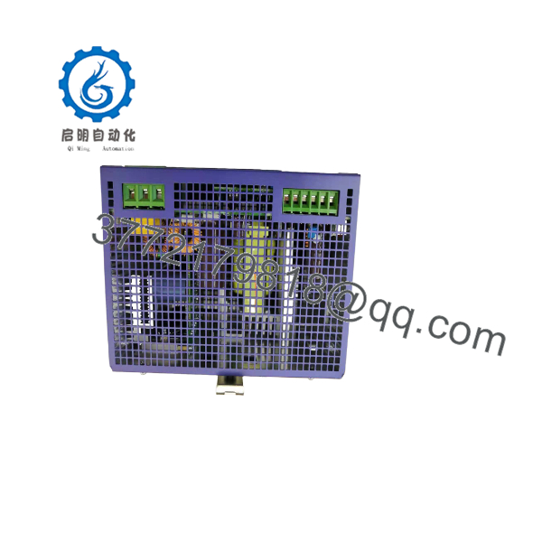
PW723
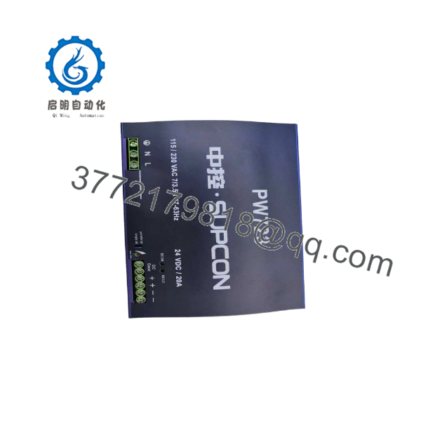
PW723
Installation & Configuration Guide
Stage 1: Pre-Installation Preparation — Approximately 5 minutes
⚠️ Safety First: The handles power at potentially hazardous levels. Notify operations, place the DCS/control station in the required safe state, and follow site lockout/tagout procedures before disconnecting the supply.
Tools Required:
- ESD wrist strap
- Insulated screwdriver appropriate for the terminal hardware
- Digital multimeter
- Wire labels
- Smartphone/camera for configuration photographs
Before Removal:
- Record the complete nameplate information.
- Photograph the AC input and DC output wiring.
- Photograph the redundancy arrangement if operates in parallel.
- Record which PW701/PW702/PW703 module is installed, if applicable.
- Verify the downstream power distribution arrangement, including PW715 where installed.
Stage 2: Removing the Old Module — Approximately 5 minutes
- Isolate the upstream AC supply.
- Verify absence of voltage with a properly rated multimeter.
- Label all input and output conductors.
- Disconnect the wiring without pulling on the conductors.
- Release the DIN-rail retaining mechanism.
- Remove from the rail.
- Inspect the wiring and terminal area for heat discoloration, loose conductors, or damaged insulation.
⚠️ Keep the removed until the replacement has operated correctly under load.
Stage 3: Installing the New Module — Approximately 5 minutes
- Verify that the replacement is the exact model.
- Compare the replacement nameplate with the removed unit.
- Check the DIN rail and mounting area.
- Install the securely on the DIN rail.
- Reproduce the original input/output wiring exactly from the photographs and wiring documentation.
- Verify polarity on the 24 VDC output.
- If the system uses parallel/redundant supplies, verify the associated redundancy module before energizing.
- Tighten terminals according to the applicable SUPCON installation specification.
Self-Checklist:
- model verified
- Input wiring verified
- 24 VDC polarity verified
- DIN-rail mounting secure
- Redundancy arrangement checked
- Downstream distribution wiring checked
- Terminal connections secure
Stage 4: Power-On & Testing — Approximately 10–15 minutes
- Measure the DC output before reconnecting sensitive downstream equipment where the installation procedure permits.
- Energize the AC input.
- Check the status/diagnostic indicators.
- Verify the DC output voltage.
- Check the load-side voltage at the distribution point.
- Confirm that the controller and I/O equipment receive stable DC power.
- Check for power-fault alarms.
- If redundant supplies are installed, verify the expected load-sharing/redundancy behavior.
- Monitor the supply under normal operating load.
The available SUPCON documentation specifically describes -family supplies as having overvoltage/overcurrent protection and power-fault diagnosis/indication.
⚠️ Do not jumper or bypass the redundancy circuitry simply to make a replacement supply start. Verify the actual power architecture first.
Frequently Asked Questions (FAQ)
What is the SUPCON ?
is a 24 VDC, 20 A system power-supply module used in SUPCON DCS installations. SUPCON project documentation explicitly identifies it as a system power supply module with a 24 V, 20 A rating.
Is an power supply?
Yes. SUPCON documentation places within the DCS control-station power architecture. It is shown alongside controllers, I/O modules, racks, and communication equipment.
Can operate in parallel?
Yes, but there is an important qualification. SUPCON’s documentation states that PW721, PW722, and require a compatible redundancy module—PW701, PW702, or PW703—when connected in parallel.
What is the output rating of ?
The documented rating is 24 VDC / 20 A. This is the key specification to match when replacing an installed .
Does use DIN-rail mounting?
Yes. SUPCON’s power-supply documentation identifies the power modules and associated redundancy modules as using standard DIN-rail mounting, with input and output connections made through terminals.
Is interchangeable with PW721 or PW722?
Do not treat the three models as automatically interchangeable. They belong to the same power-supply family, but their electrical ratings and system application should be checked against the installed configuration. Match the exact original model first.
What should I check before buying a replacement ?
For a plant spare, record the complete model marking, hardware revision if present, input requirements, output rating, wiring arrangement, and redundancy configuration. Also confirm whether the unit is New Original, New Surplus, or Refurbished/Tested. For a running DCS, retaining one tested spare on site can avoid an extended control-station outage when the installed supply fails.



