
 WhatsApp: +86 16626708626
 Email:
  Phone: +86 16626708626
Description
Key Technical Specifications
| Parameter | Value |
|---|---|
| Manufacturer | SUPCON |
| Model Number | TB366-DU |
| Alternate Marking | TB366-DU |
| Product Family | SUPCON ECS-100 / XP366 digital input interface family |
| Product Type | Digital input terminal board / field wiring termination board |
| Primary Function | Provides field wiring termination and signal interface for a compatible digital input card |
| Associated I/O Card | XP366 intelligent 16-channel digital input card |
| I/O Card Operating Modes | XP366 supports single-card and redundant operating modes |
| Field Signal Category | Discrete / digital input signals |
| Terminal-Power Markings | 24V1, GND1, 24V2, GND2 markings reported on listed board versions |
| Board Revision Reference | V1.1 reported on market listings; verify exact installed revision before procurement |
| PCB Identification Marking | 94V-0 and E302598 reported on market listings |
| Approximate Weight | 320 g reported on market listings |
| System Interface | Uses dedicated field cable or compatible terminal-board connection to the XP366 card; confirm cable type and pinout from the installed SUPCON system drawings |
| Related TB366 Variants | TB366-220VU, TB366-48VU, TB366-GPRHU, and -NPNU are different terminal-board variants; they are not automatic substitutes |
| Lifecycle Status | Legacy DCS field-termination spare; confirm exact SUPCON part lifecycle and current supply availability before a last-time-buy |
| Stocking Recommendation | Min: 1 per critical common field termination design or per cabinet cluster; Max: 2 only where installed base, fault history, and lead time variability justify added buffer stock |
SUPCON-related references identify the XP366 as an intelligent 16-channel digital input card that can operate in single-card or redundant modes and can connect to -DU, -220VU, -48VU, -GPRHU, -NPNU, and safety-barrier terminal-board variants. The -DU must therefore be matched to the installed field wiring and XP366 application, not selected solely because it belongs to the family.
Product Introduction & Supply Chain Strategy
The SUPCON -DU is a digital input field-termination board used with the I/O card in compatible SUPCON DCS installations. It provides a structured interface between field contact signals, field 24 V DC distribution, cabinet wiring, and the digital input card. It supports maintainable marshalling by keeping field terminals separate from the active I/O electronics.
This product is a Brand New Surplus unit. It is not used, not pulled from a decommissioned plant, and not refurbished. All modules undergo rigorous quality verification to ensure OEM-level reliability. The board is low in unit cost but can cause a long outage if it is unavailable during a field wiring fault. Keep targeted buffer stock, confirm cabinet commonality across sites, and use vendor consolidation to control carrying cost. Avoid buying other variants without a pinout and field-voltage review.
Installation & Configuration Guide
Stage 1: Pre-Installation
- Obtain approved DCS maintenance authorization and coordinate the work with operations, the control-room operator, instrument technicians, and the responsible process engineer.
- Identify all field points connected through the -DU. These may include status contacts, limit switches, relay outputs, motor auxiliary contacts, valve-position switches, alarm contacts, permissives, and equipment interlocks.
- Record the DCS controller, I/O cabinet, node, rack, slot, card position, redundancy status, terminal-board designation, field cable number, terminal-strip references, and associated loop drawings.
- Back up the applicable DCS configuration, channel mapping, point database, alarm limits, logic references, interlock drawings, cause-and-effect documentation, and maintenance records.
- Review active alarms, forced points, bypasses, inhibited interlocks, simulated inputs, redundant-card state, and current process conditions before taking the board out of service.
- Place the process in an approved safe state. If signals affect safety, shutdown, permissive, turbine, burner, or equipment-protection logic, obtain the required bypass authorization and follow the site safety procedure.
- Apply lock-out/tag-out to relevant field power supplies and 24 V DC circuits where the approved procedure requires it.
- Verify the absence of unintended voltage before handling terminal wiring. A digital input terminal board can contain external field voltage even when the DCS card or cabinet is isolated.
- Wear a grounded ESD wrist strap when handling the board, field cable connector, or adjacent hardware.
- Photograph the insta from all sides. Capture terminal numbers, wire colors, wire markers, 24V1/GND1 and 24V2/GND2 connections, shield terminations, jumpers, board revision, field cable, connector orientation, and mounting hardware.
- Compare the replacement board’s complete marking with the installed unit. Ve designation, board revision, connector layout, terminal layout, power-terminal markings, and mounting pattern.
- Do not assume that -48VU, -220VU, -GPRHU, or -NPNU is interchangeable. These variants are associated with different field-interface applications.
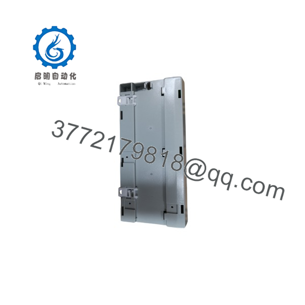
TB366-DU
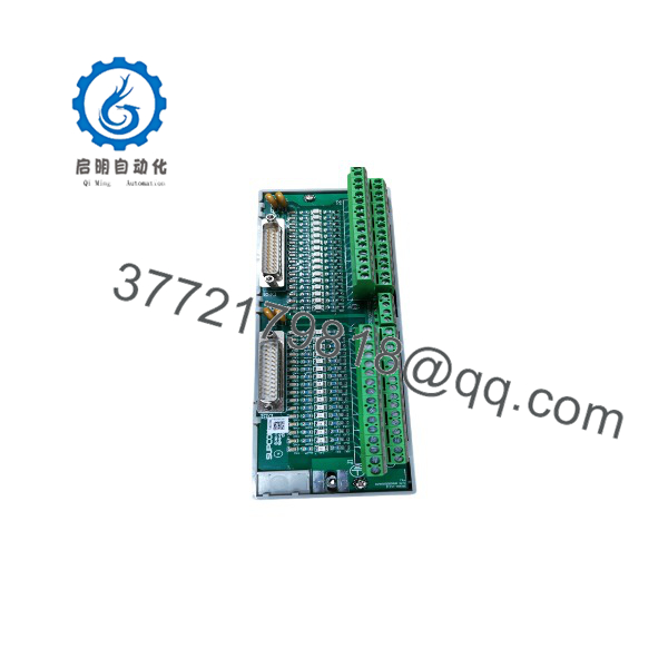
TB366-DU
Stage 2: Removal
- Confirm that every affected point is safe, bypassed under formal control where required, or isolated according to the maintenance plan.
- Label each field conductor individually before removal, even when existing labels are present. Compare each label against the approved loop drawing and your photographs.
- Disconnect field power feeds only after confirming their source and destination. Preserve the distinction between 24V1/GND1 and 24V2/GND2 circuits where installed.
- Disconnect the dedicated cable or connector between and the input card by its housing. Do not pull on the cable bundle.
- Remove terminal wiring in an organized sequence. Keep wire markers intact and avoid stressing ferrules, shields, or adjacent terminals.
- Remove retaining screws, clips, DIN-rail hardware, or standoffs according to the installed cabinet design.
- Lift the board carefully, avoiding flexing the PCB or contacting component surfaces.
- Inspect the field cable, connectors, terminal screws, terminal blocks, mounting hardware, cabinet grounding, and adjacent wiring for corrosion, looseness, overheating, contamination, or insulation damage.
- Preserve the removed board in ESD-safe packaging and label it with cabinet location, card association, fault symptoms, removal date, and asset number.
Stage 3: Installation
- Compare the New Sur side by side with the removed board. Confirm model marking, board revision, PCB markings, terminal layout, connectors, mounting points, and field-power terminal positions.
- Mount the terminal board in the original orientation and location. Secure all screws, clips, or DIN-rail retention hardware.
- Reconnect the interface cable to the card or associated field cable assembly. Confirm connector keying and orientation before applying force.
- Reconnect protective earth, shield drains, or cabinet grounding hardware exactly as documented. Do not create new shield grounds without an approved drawing change.
- Restore field wiring one terminal at a time using the recorded terminal schedule. Do not wire from memory.
- Reconnect 24 V DC field supplies according to the original terminal designations. Verify polarity and separation of redundant or grouped supplies before energization.
- Tighten terminal screws to the applicable manufacturer torque specification. Loose terminals can generate intermittent field-input alarms that resemble failed I/O cards.
- Confirm that wire insulation does not enter the clamping area and that no exposed conductor can contact adjacent terminals.
- Recheck every termination against the loop drawing, field cable number, channel list, and photographs before restoring power.
Stage 4: Power-On & Testing
- Before applying field power, test each 24 V DC field-power feed for correct polarity and absence of short circuits to ground.
- Energize the field supply according to the approved cabinet startup procedure and monitor for excessive current, blown fuses, unexpected alarm states, or voltage drop.
- Confirm that the card reports healthy status and that any redundant I/O arrangement returns to the expected operating state.
- Verify all affected digital input points one at a time. Compare field-device state, terminal voltage, DCS point status, alarm status, logic status, and operator display.
- Test critical points using approved field simulation or functional-test procedures. Do not force or simulate shutdown-related signals without process-owner authorization.
- Verify that the system distinguishes normal, alarm, open-circuit, and de-energized conditions as designed for each loop.
- Check DCS event logs, alarm history, and redundant I/O diagnostics for channel faults, communication errors, mismatch indications, or nuisance transitions.
- Remove temporary bypasses only under approved control. Obtain operations acceptance before returning affected interlocks, permissives, and process equipment to normal service.
- Record the insta board revision, serial or traceability marking, cabinet location, association, test results, installation date, technician, and remaining buffer-stock quantity.
Firmware/Software Versions & Upgrade Notes
- Recommended firmware version: is a passive or interface-level field-termination board and does not normally carry user-managed firmware. Compatibility depends on the associated card, field cable, terminal-board revision, field voltage arrangement, DCS database configuration, and process logic.
- compatibility: SUPCON-related reference material identi as one of the terminal-board options for the intelligent 16-channel digital input card. Verify the exact card revision, cabinet configuration, and cable assignment before installing the board.
- No DIP-switch assumption: Do not assume has standard field-configurable DIP switches or jumpers. Inspect the existing board and approved drawings for any installed links, power-distribution jumpers, shields, or terminal assignments.
- Channel mapping: Preserve the DCS point-to-channel mapping before replacement. A terminal-board wiring error can place a field contact on the wrong input and create a false process status or missed trip condition.
- Variant compatibility warning: -48VU is described as a 32-channel 48 V DC digital input terminal board. This does not confirm compatibility , which must be matched to its installed application and wiring scheme.
- Backward compatibility: An ear revision may differ in terminal marking, component population, connector assignment, power-distribution arrangement, or field cable design. Match board revision where possible.
- Forward compatibility: A later replacement board may require a different field cable, I/O card revision, or revised terminal schedule. Treat any difference in layout or markings as an engineering change requiring drawing review.
- Upgrade warning: Do not revise firmware, DCS controller firmware, I/O database, or process logic during an emergency terminal-board replacement unless the existing configuration is unavailable and the change has formal approval.
- Downgrade warning: Do not restore an older DCS configuration without checking point mapping, logic revision, alarm settings, and compatibility with the installed I/O system.
- Spare-control recommendation: Store each New Sur with cabinet location, card association, board-revision record, field-cable part number, wiring diagram, terminal schedule, loop-test procedure, and current DCS configuration reference.
Frequently Asked Questions (FAQ)
Are these really new units?
Yes. This supply standard applies to New Original / New Surplus boards only. A New Sur should show no field-wire insertion marks, damaged terminals, bent connector contacts, altered components, contamination, corrosion, heat discoloration, or evidence of installation. Incoming QC should verify model markings, board revision, terminal layout, connector condition, mounting hardware, PCB identification markings, ESD-safe packaging, and available traceability records.
Why is New Surplus pricing lower than OEM new but higher than lower-cost alternatives?
OEM-new pricing reflects current manufacturer channels and standard support structures. New Surplus pricing reflects the cost of locating, validating, storing, and warranting genuine DCS spares. Lower-cost alternatives may carry damaged terminals, altered jumpers, incorrect board revisions, cracked solder joints, contamination, or prior field-wiring stress. The board may be inexpensive, but an incorrect or failed field-termination board can create false status signals, process trips, missed alarms, and extended troubleshooting labor.
Is obsolete or EOL?
Treat as a legacy SUPCON DCS field-interface spare until SUPCON or an authorized supplier confirms current lifecycle status. Available public references show continuing market availability and association with the card, but they do not establish current factory production, official replacement status, or regional service support.
For a critical input cabinet, keep one verified buffer stock board on-site or within a defined cross-site recovery window. Use a last-time-buy only after reviewing commonality, installed base, supplier lead time variability, cabinet environment, fault history, and the cost of a prolonged I/O outage.
Can I hot-swap?
Do not assume hot-swap capability. interfaces with external field wiring and 24 V DC power distribution, so removal can interrupt live process signals or create unintended digital input states. Isolate field circuits, apply approved bypasses, and follow the DCS maintenance procedure unless the system documentation explicitly authorizes online replacement.
Will replacing the terminal board erase DCS programming?
No. The DCS application and configuration normally reside in the controller and I/O system, not in the terminal board. However, incorrect reconnection can map field devices to the wrong channels or reverse field power. Back up the DCS configuration and verify every affected input after installation.
Can I substitute another terminal board?
Not without an engineering-approved cross-reference. SUPCON references iden, -220VU, -48VU, -GPRHU, and -NPNU as distinct options for the family. Their field voltage, channel count, signal type, terminal layout, and cable compatibility can differ.
Match the exact board designation, installed revision, field voltage, connector pinout, terminal schedule, cable type, and application before authorizing any substitution.
What warranty and QC documentation should accompany the spare?
Specify a written 12-month warranty, subject to ESD-safe storage, correct installation, and proper environmental conditions. Request model and board-revision photographs, terminal and connector inspection records, PCB-condition verification, field-power continuity checks where appropriate, functional-test evidence with a compatible system or test fixture, and final QC sign-off. Retain these records with the DCS asset file, loop drawings, terminal schedule, and commissioning checklist so maintenance can restore field inputs quickly and accurately.



