
 WhatsApp: +86 16626708626
 Email:
  Phone: +86 16626708626
Description
Key Technical Specifications
| Parameter | XP251-1 Specification |
|---|---|
| Manufacturer | SUPCON / Zhejiang SUPCON |
| System | WebField JX-300XP |
| Module type | DCS power supply module |
| Input voltage | 220 VAC ±10% |
| Input frequency | 50 Hz ±3 Hz |
| Output 1 | 5 VDC |
| Output 2 | 24 VDC |
| 5 V rated current | 5 A |
| 24 V rated current | 6 A |
| Single-module output | 150 W |
| Efficiency | 80% rated |
| Ripple coefficient | ≤1% |
| Operating temperature | 0 to 50 °C |
| Operating humidity | 10–90% RH, noncondensing |
| Storage/transport temperature | -40 to +70 °C |
| Installation rack | XP251 |
| Maximum modules per rack | 4 |
| Insulation | Class I safety requirements |
SUPCON’s JX-300XP selection documentation describes XP251-1 as a double-output power supply module that simultaneously provides 5 V and 24 V. The documented single-power-supply output is 150 W, and the XP251 rack can hold four modules.
A separate XP251-1 technical reference specifies 220 VAC ±10%, 50 Hz ±3 Hz, 5 V output at 5 A, 24 V output at 6 A, approximately 80% rated efficiency, and ripple coefficient ≤1%.
Product Introduction
The SUPCON XP251-1 is the dedicated power supply module used with the WebField JX-300XP DCS. It converts the incoming 220 VAC supply into the DC rails required by the control-system hardware, providing separate 5 VDC and 24 VDC outputs. The module installs into an XP251 power-supply rack, which supports up to four -1 units.
The dual-output architecture is important when maintaining legacy JX-300XP installations. The 5 V rail supports the system electronics, while the 24 V rail supplies the corresponding field/control-system power requirements. SUPCON documentation also specifies redundant power-supply configuration for I/O modules, making the number and arrangement of installed -1 units an important part of system maintenance planning.
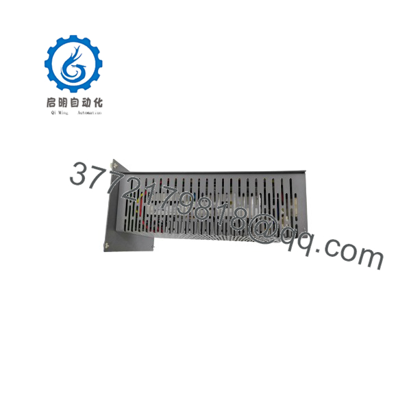
XP251-1
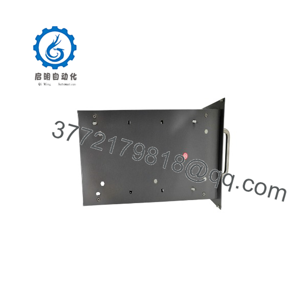
XP251-1
Installation & Configuration Guide
Stage 1 — Pre-Installation Preparation (~5 minutes)
- Apply the plant’s lockout/tagout procedure before working on the DCS power rack.
- Identify the rack and the d position.
- Record the status of the 5 V, 24 V, and FAIL indicators.
- Photograph the front panel and rear connectors.
- Confirm the incoming AC supply and rack wiring.
- Check whether the system uses a redundant power-supply arrangement.
- Prepare an ESD strap, insulated tools, multimeter, wire labels, and the original system documentation.
⚠️ Do not remove a power module from a live rack unless the specific JX-300XP installation procedure explicitly permits it. Treat the 220 VAC input as hazardous.
Stage 2 — Removing the Existing Module (~5 minutes)
- Swite front-panel power switch to the OFF position where applicable.
- Isolate the associated AC supply.
- Verify the absence of hazardous voltage with an appropriate meter.
- Disconnect the rear connectors.
- Loosen the four front-panel mounting screws.
- Slide the power module out of the rack using the guide rails.
- Inspect the rack connector and module contacts for contamination or damage.
The avae service documentation describes installation as sliding the power-supply module into the plastic guide rail, pushing it fully into position, securing the four front screws, and then connecting the rear connectors. Removal follows the reverse sequence after switching off the module.
Stage 3 — Installing the Replacement (~5 minutes)
- Verify that the replacement is marked .
- Compare the front-panel indicators, switch, connector arrangement, and mechanical dimensions with the removed unit.
- Slide the module into the rack guide rails.
- Push the module fully into position.
- Tighten the four front-panel screws.
- Reconnect the rear connectors.
- Confirm that AC input wiring and DC output connections are correctly seated.
⚠️ Do not ce with the rack itself. is the power-supply; is the individual power-supply module. SUPCON documentation explicitly distinguishes these two components.
Stage 4 — Power-On & Testing (~10–15 minutes)
- Perform a final wiring inspection.
- Verify the AC input voltage before energizing.
- Restore power to the module.
- Confirm the 5 V and 24 V indicators illuminate normally.
- Confirm that the FAIL indicator remains off.
- Measure the DC output rails where the maintenance procedure provides appropriate test points.
- Check connected DCS racks for power-related alarms.
- Verify controller and I/O module operation.
- If redundant supplies are installed, confirm the expected redundant power arrangement.
- Record measured voltages and module identification for the maintenance log.
e documentation states that abnormal system voltage causes the FAIL indication to activate while the corresponding 5 V and 24 V indicators extinguish; normal operation is indicated by the 5 V and 24 V indicators being on with FAIL off.
Technical Pitfall & Survival Guide
Do not diagnn failure solely from the DCS going offline.
A failed rack connector, AC distribution problem, loose rear connector, overloaded DC rail, or fault in downstream equipment can produce similar symptoms.
The useful first check is simple: measure the incoming AC, then verify the 5 V and 24 V rails independently. If one rail is missing while the other remains normal, the fault is much easier to localize.
For spare-parts inventory, keep the module andXP251 rack separately identified. They are different procurement items.
Frequently Asked Questions (FAQ)
What is the N ?
e is a dual-output power supply module for the SUPCON WebField JX-300XP DCS. It provides both 5 VDC and 24 VDC and installs into the power-supply rack.
What voltage doe accept?
The documented input is 220 VAC ±10% at 50 Hz ±3 Hz. Confirm the actual plant distribution voltage before installation.
What ae output ratings?
The documented outputs are 5 VDC at 5 A rated current and 24 VDC at 6 A rated current. The single-module output rating is 150 W.
Hoy modules fit in an rack?
The power-supply rack can accommodate up tr power-supply modules.
Does the JX-300XP support redundant power supplies?
Yes. SUPCON’s JX-300XP documentation specifies redundant configuration for the power supplies serving I/O modules. The exact redundancy arrangement should be checked against the installed rack architecture before removing any module.
s interchangeable with other SUPCON power modules?
Do not assume interchangeability based on output voltage alone. Market listings sometimesp with other SUPCON power modules such as PW722, FW252-03A, FW252-04A, or SP251-1, but these are separate model designations. The correct replacement should be established from the original module’s complete identification and the JX-300XP rack configuration.
What should procurement verify before buyn ?
Verify the model number, physical condition, front-panel labeling, connector condition, output-voltage test results, and compatibility with the installed JX-3XP251 rack. For a used or surplus unit, request photographs of the nameplate and a functional test record rather than relying solely on a seller’s “new original” description.



