
 WhatsApp: +86 16626708626
 Email:
  Phone: +86 16626708626
Description
Key Technical Specifications
| Parameter | Value |
|---|---|
| Model | BG0090 PC0006 |
| Manufacturer | TEAM |
| Series | BG0090 |
| Product Classification | Industrial automation module; exact OEM function requires verification |
| Reported Supply Voltage | 24 V DC |
| Reported Rated Current | 6 A |
| Reported Peak Current | 10 A |
| Reported Rated Power | 144 W |
| Reported Control Modes | Position, speed, torque |
| Reported Communication Interfaces | RS-232, RS-485, CANopen |
| Reported Encoder Types | Incremental, absolute |
| Reported Dimensions | 110 × 70 × 30 mm |
| Other Reported Classification | DCS/PLC control module |
| Reported Protocols in Alternate Listing | EtherNet/IP, Modbus TCP |
| Reported I/O in Alternate Listing | 16 digital inputs / 16 digital outputs |
Technical caution: The published data is not sufficiently consistent to treat all values above as confirmed OEM specifications. For example, one source identifies BG0090 PC0006 as a servo motor drive with 6 A rated current and CANopen, while another describes it as a DCS/PLC control module with EtherNet/IP and Modbus TCP.
For a replacement purchase, verify the nameplate, PCB markings, connector arrangement, hardware revision, and original TEAM documentation before using electrical or communication specifications for installation.
Product Introduction
The TEAM BG0090 PC0006 is an industrial automation component associated with the TEAM BG0090 product family. Publicly available listings classify it inconsistently, with one source identifying it as a servo drive module and another as a DCS/PLC control module.
That distinction matters during replacement. Do not select the unit solely from the BG0090 or PC0006 marking. Match the complete part number, hardware revision, connectors, electrical ratings, and installed system before commissioning.
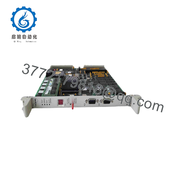
BG0090 PC0006
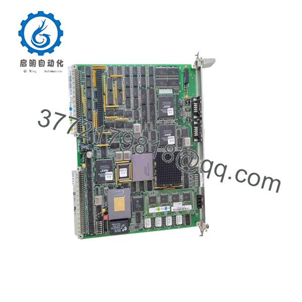
BG0090 PC0006
Installation & Configuration Guide
Stage 1: Pre-Installation Preparation — Approximately 10 Minutes
⚠️ Safety First: Put the controlled equipment into its approved maintenance state before removing PC0006. Follow the site’s lockout/tagout procedure and isolate all applicable power sources.
Tools Required
- ESD wrist strap
- Appropriate Phillips screwdriver
- Digital multimeter
- Wire labels
- Smartphone or camera
- Existing wiring diagram
- Original equipment documentation
Data Backup
- Record the complete marking.
- Photograph the module from several angles.
- Photograph every connector before removal.
- Record visible PCB or hardware revision numbers.
- Photograph switches, jumpers, and termination settings.
- Record the existing controller/drive parameters.
- Save the current configuration if the installed system provides an approved backup function.
⚠️ Because public specifications for this part are inconsistent, the physical unit currently installed in your system is the most important reference.
Stage 2: Removing the Old Module — Approximately 5 Minutes
- Confirm the machine or process is in a safe state.
- Isolate the module’s power supply.
- Verify absence of hazardous voltage with an appropriate meter.
- Remove the enclosure cover or module retaining hardware.
- Label every connector and conductor before disconnecting it.
- Disconnect the wiring without pulling on individual wires.
- Release the module’s retaining mechanism.
- Pull the module straight out where the mechanical design permits.
- Inspect connectors for oxidation, bent contacts, contamination, or heat damage.
⚠️ Keep the original PC0006 until the replacement has passed commissioning. If the replacement behaves differently, the original hardware provides a valuable reference for connector orientation and configuration.
Stage 3: Installing the New Module — Approximately 5–10 Minutes
- Put on the grounded ESD wrist strap.
- Confirm the replacement marking is exactly .
- Compare the housing, connectors, PCB revision, and mounting arrangement with the removed unit.
- Do not install the module if the connector layout differs without documented OEM confirmation.
- Replicate all documented switches and jumpers from the original unit.
- Install the module without forcing the connectors.
- Reconnect wiring according to the photographs and approved drawings.
- Confirm that all connectors are fully seated.
- Check that no wire is trapped beneath the module or cover.
Self-Checklist
- Exact part number verified
- Hardware revision checked
- Connector arrangement matches
- Jumpers/DIP switches checked
- Wiring labeled and restored
- Module mechanically secured
- ESD precautions maintained
Stage 4: Power-On & Testing — Approximately 10 Minutes
- Perform a final visual inspection.
- Check the applicable DC supply before energizing the module.
- Restore power according to the equipment manufacturer’s procedure.
- Observe all status LEDs.
- Check for abnormal current draw, alarms, or fault indications.
- Connect the approved programming or drive configuration software where applicable.
- Verify communication with the host controller.
- Compare the loaded parameters against the backup.
- Perform a controlled dry run.
- Test the relevant I/O, enable, feedback, and communication functions before returning the equipment to production.
⚠️ Do not assume that the communication interface is CANopen, EtherNet/IP, Modbus TCP, RS-485, or RS-232 solely from online reseller descriptions. Available sources disagree on these specifications.
If the unit fails to communicate, first check power, connector seating, address/configuration settings, wiring, hardware revision, and the host-system configuration before replacing additional components.
Frequently Asked Questions (FAQ)
Q1. What is TEAM ?
is a TEAM-branded industrial automation component associated with the family. Public listings disagree about its exact role: one identifies it as a servo drive module, while another calls it a DCS/PLC control module.
Q2. Is a servo drive?
One published listing explicitly describes TEAM as a servo motor drive module, specifying position, speed, and torque control, along with RS-232, RS-485, and CANopen interfaces. However, other listings classify the same part number differently.
For procurement, I would verify the actual nameplate and application rather than relying on the generic description “servo drive.”
Q3. What voltage does use?
A public listing specifies 24 V for the unit. Another listing also gives 24 V DC. However, because the sources disagree about the product’s fundamental classification, confirm the electrical rating against the actual unit and OEM documentation before energizing a replacement.
Q4. Does support CANopen?
One published specification explicitly lists CANopen, together with RS-232 and RS-485. Another listing instead identifies EtherNet/IP and Modbus TCP. That conflict means CANopen should be treated as reported information rather than a confirmed specification until the installed hardware or OEM documentation is checked.
Q5. Can I use another module as a direct replacement?
Not automatically. Match , the hardware revision, electrical ratings, connectors, configuration settings, and host-system requirements. A module from the same family can have a different function or interface.
Q6. Is obsolete?
I could not verify an authoritative TEAM lifecycle notice establishing its current production or obsolescence status. The part continues to appear in third-party industrial-component listings, including a component index that specifically associates TEAM with .
For an obsolete or long-discontinued control system, request the actual unit photographs, nameplate information, manufacturing date if available, and test report before purchasing.
Q7. What condition should I request when buying ?
Specify the condition explicitly: New Original / New Surplus, Factory Sealed, or Refurbished and Tested. For a replacement going into a running industrial system, also request photographs of the actual part number and hardware revision rather than relying only on a catalog photograph.



