
 WhatsApp: +86 16626708626
 Email:
  Phone: +86 16626708626
Description
Key Technical Specifications
| Parameter | APS-DD-2 Specification |
|---|---|
| Manufacturer | Techsoft |
| Model | APS-DD-2 |
| Product Type | Digital direct-drive servo driver |
| Input Voltage | 18–160 VDC |
| Continuous Output Current | 12 A RMS |
| Peak Output Current | 36 A RMS |
| Peak Duration | 1 second maximum |
| Control Processor | 32-bit floating-point DSP |
| Maximum Motor Power | 1,000 W |
| Position Feedback | Incremental encoder |
| Encoder Rate | 5 M lines/s raw; 20 M lines/s with 4× multiplication |
| Hall Feedback | U/V/W digital Hall |
| Sensorless Feedback | Back-EMF |
| Control Modes | Position, velocity, torque, electronic gearing, electronic cam |
| Analog Command | ±10 V velocity/torque input |
| Pulse Command | Step/direction |
| Digital Inputs | 6 isolated inputs |
| Digital Outputs | 2 programmable outputs |
| PC Interface | RS-232 |
| Position Loop Bandwidth | Up to 800 Hz |
| Dimensions | 168 × 100 × 31 mm |
| Operating Temperature | 0–50 °C |
| Weight | Approx. 0.41 kg |
These specifications come from the available APS-DD-2 technical listing. Because I could not locate an accessible OEM datasheet from Techsoft, electrical and mechanical values should be checked against the actual nameplate/manual before publishing them as final procurement specifications.
Product Introduction
The Techsoft APS-DD-2 is a compact digital servo amplifier intended for direct-drive motion applications. It supports DDR torque motors, DDL linear motors, and voice-coil actuators, with closed-loop position, velocity, and torque control handled by a 32-bit DSP.
The driver accepts 18–160 VDC and provides 12 A RMS continuous output current, with a 36 A RMS short-duration peak rating. Its feedback architecture supports incremental encoders as well as Hall and sensorless configurations, making it suitable for precision positioning equipment where a conventional mechanical transmission is undesirable.
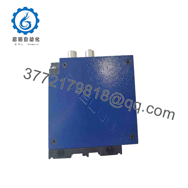
APS-DD-2
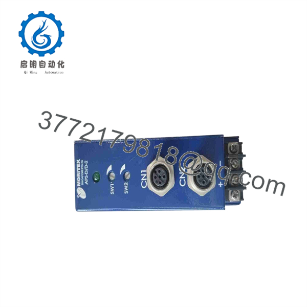
APS-DD-2
Installation & Configuration Guide
Stage 1 — Pre-Installation Preparation
- Confirm the exact model marking as APS-DD-2.
- Verify the motor’s rated voltage, current, power, feedback type, and phase wiring.
- Confirm that the DC supply remains within the 18–160 VDC input range.
- Back up the existing servo parameters and motion program.
- Record encoder resolution, direction, electronic gearing, current-loop settings, and position-loop parameters.
- Disconnect DC bus power before wiring the driver.
⚠️ A 160 VDC maximum bus is hazardous. Use an appropriate lockout/tagout and DC-bus discharge procedure.
Stage 2 — Removing the Existing Driver
- Stop the machine and place it in its approved maintenance state.
- Isolate the DC power supply.
- Verify that the DC bus has discharged to a safe voltage.
- Label motor, encoder, I/O, and communication wiring.
- Disconnect the motor and feedback connectors.
- Remove the existing amplifier from its mounting position.
- Inspect the motor and encoder cables for insulation or connector damage.
Stage 3 — Installing the APS-DD-2
- Confirm motor compatibility before connecting the output stage.
- Mount the securely with adequate ventilation.
- Connect the DC bus with correct polarity.
- Connect the motor phases according to the manufacturer’s wiring configuration.
- Connect the encoder or selected feedback device.
- Connect the ±10 V or step/direction command interface as applicable.
- Connect required digital inputs and outputs.
- Connect the RS-232 interface if PC configuration is required.
⚠️ Never reverse the DC input polarity. The available technical documentation specifically identifies reverse-polarity connection as a condition that can damage the internal power stage.
Stage 4 — Power-On & Testing
- Apply control power with the motor mechanically secured.
- Verify that no fault condition is present.
- Confirm feedback polarity and encoder counts.
- Perform motor phase alignment or commissioning procedure.
- Start with a low-speed/low-command test.
- Verify positive and negative motion directions.
- Check position following error and velocity response.
- Gradually increase operating commands to the qualified machine settings.
- Verify over-current, over-voltage, encoder-loss, and over-temperature protection.
⚠️ Do not run the motor at full current during the first commissioning test. Validate feedback polarity and motor phase sequence first.
FAQ
What is the ?
The is a digital direct-drive servo amplifier designed for DDR torque motors, DDL linear motors, and voice-coil actuators.
What DC voltage does it accept?
The listed input range is 18–160 VDC.
What is the continuous output-current rating?
The listed continuous output rating is 12 A RMS, with a peak rating of 36 A RMS for up to one second.
What feedback devices are supported?
The available specification lists orthogonal incremental encoders, digital U/V/W Hall sensors, and back-EMF sensorless feedback. Incremental encoder processing is specified up to 5 M lines/s raw or 20 M lines/s using 4× multiplication.
Does support position control?
Yes. The listed control modes include position, velocity, and torque closed-loop control, as well as electronic gearing and electronic cam functions.
What command interfaces are available?
The driver supports ±10 V analog velocity/torque commands and step/direction pulse commands. It also provides six isolated digital inputs and two programmable digital outputs.
Is suitable for a 1 kW direct-drive motor?
The available specification lists 1,000 W as the maximum supported motor power. Actual compatibility still depends on the motor’s bus voltage, continuous/peak current, feedback device, and required acceleration profile.



