
 WhatsApp: +86 16626708626
 Email:
  Phone: +86 16626708626
Description
Key Technical Specifications
| Parameter | Specification Value |
| Part Number | 1381-645294-12 |
| Manufacturer | Tokyo Electron Limited (TEL) |
| Target Equipment Class | Semiconductor Coater/Developer Tracks, Etch Systems, Thermal Processing Systems |
| Board Type | Multi-Layer High-Density Signal Distribution / IMC PCB |
| Connector Interface | Industrial multi-pin ribbon headers and edge card bus connectors |
| Operating Voltage | Low-voltage logic DC rails (5 V DC / 24 V DC backplane supplied) |
| Surface Treatment | Cleanroom-grade anti-gas out conformal coating |
| Operating Temperature | +10°C to +40°C (50°F to 104°F Class 1/10 Fab environment) |
| Storage Temperature | −20°C to +60°C (−4°F to 140°F) |
| Relative Humidity | 20% to 80% non-condensing |
| Mounting Style | Rack-slide slot insertion with retention lock brackets |
Product Introduction & Supply Chain Strategy
The TEL 1381-645294-12 is a specialized Inter-Module Communication PCB assembly engineered for Tokyo Electron wafer processing tools. Positioned within the main electronic card cage, it serves as the critical communication spine, interconnecting process module controllers, mass flow controllers, robot motion cards, and main host computers.
Securing the 1381-645294-12 as New Surplus is a high-ROI strategy for semiconductor fabrication facilities and maintenance managers. Unplanned tool downtime in a 300mm or 200mm fab can cost thousands of dollars per hour in stalled wafer starts. Sourcing verified New Surplus eliminates the risk of contaminated or degraded components typical of second-hand fab boards while bypassing extended OEM procurement lead times.
Installation & Configuration Guide
Stage 1: Pre-Installation (Prep & Safety)
- Initiate a graceful tool shutdown via the TEL main system software interface and perform Lock-Out/Tag-Out (LOTO) on the main tool power distribution unit (PDU).
- Put on a cleanroom-compliant grounded ESD wrist strap before opening the electronics bay.
- Inspect the replacement 1381-645294-12 board for pristine edge-connector plating and pin alignment.
- Document all wire harness routing and connector positions using a digital photo or wiring log.
Stage 2: Removal
- Unplug all multi-pin harness connections attached to the front face of the active 1381-645294-12 module.
- Loosen the upper and lower captive thumbscrews securing the board to the card cage frame.
- Carefully disengage the board ejector levers and slide the PCB straight out along the nylon guide tracks.
- Immediately store the removed unit in an ESD-shielded cleanroom bag.
Stage 3: Installation (Clone & Seat)
- Verify that any hardware jumpers or address DIP switch arrays on the new 1381-645294-12 match the original board configuration identically.
- Align the top and bottom edges of the module with the card cage guide rails.
- Slide the board inward until the backplane connectors align, then press the ejector levers inward to fully seat the board.
- Tighten the top and bottom retaining screws to secure the card against operational vibration.
- Reconnect all labeled wire harnesses until locking clips snap shut.
Stage 4: Power-On & Testing
- Restore PDU main breaker power and reboot the TEL system controller software.
- Monitor the initial hardware handshakes during the boot sequence to verify that all sub-module communication links initialize cleanly without bus timeout alarms.
- Execute a dry-run diagnostic routine on the tool to verify error-free signal transmission across the module.
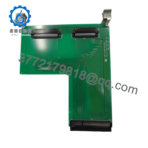
1381-645294-12
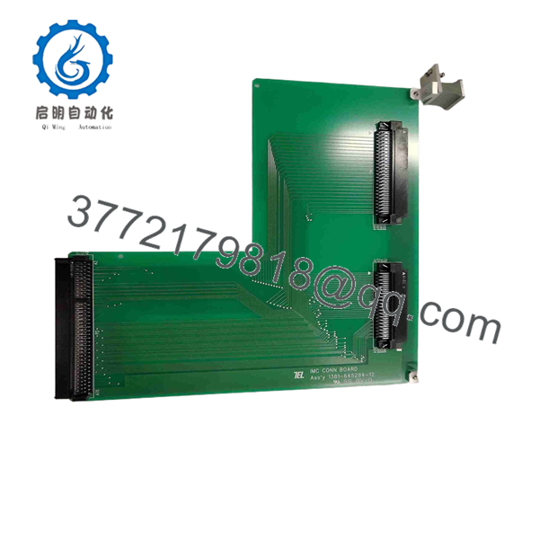
1381-645294-12
Firmware/Software Versions & Upgrade Notes
The TEL 1381-645294-12 operates as a hardware-level signal distribution interface and does not contain user-accessible flash firmware.
- System Compatibility: Compatible with designated TEL tool card cages utilizing the 1381-series backplane architecture.
- Revision Control: Match the -12 revision suffix to your existing bill of materials. The suffix code verifies pinout assignments and circuit trace revisions matched to specific tool generation requirements.
- ESD Sensitivity: Always observe Class 0 ESD handling protocols during installation; static discharge can degrade micro-traces on high-density multi-layer boards.
Frequently Asked Questions (FAQ)
Q: Is this TEL 1381-645294-12 board brand new or has it been pulled from a decommissioned fab tool?
A: This product is a Brand New Surplus unit. It is not used, not pulled from a decommissioned plant, and not refurbished. All modules undergo rigorous quality verification to ensure OEM-level reliability.
Q: Why choose New Surplus over a cheaper refurbished fab board?
A: Our pricing reflects the cost of securing genuine New Surplus inventory globally. It may be 20–30% higher than a refurbished gamble, but it is substantially less than OEM list prices, and it buys you 100% peace of mind. Refurbished fab electronics often carry unseen thermal stress micro-cracks or chemical exposure residue that causes random signal dropouts mid-process, ruining expensive wafer lots.
Q: Does replacing this board require recalibrating tool process parameters?
A: No process recipe recalibration is needed. Because the 1381-645294-12 acts as a digital/analog signal routing interconnect, recipe parameters remain intact within the main host controller memory.
Q: Are any DIP switch configurations required during replacement?
A: Always verify hardware jumpers and DIP switch blocks against the board being replaced before powering on the tool. Matching physical switch settings ensures correct bus node addressing and signal termination.
Q: What warranty is included with this New Surplus TEL module?
A: We back this board with a full 1-year functional replacement warranty, ensuring your fab maintains continuous production capability.



