
 WhatsApp: +86 16626708626
 Email:
  Phone: +86 16626708626
Description
Key Technical Specifications
| Parameter | Value |
|---|---|
| Manufacturer | Tokyo Electron (TEL) |
| Part Number | 1381-648241-15 |
| Board Designation | TVB6003-1/EMIC / TVB6003-1 EIMC |
| Product Type | Equipment Interface / Motion Control PCB |
| Product Family | TEL TVB-6003 Series |
| Primary Application | TEL semiconductor manufacturing equipment |
| Board Function | Equipment interface and control processing |
| Form Factor | Rack/card-style PCB assembly |
| Host Equipment | TEL process equipment |
| Communication / Interface | Machine-specific; verify equipment schematic |
| Supply Voltage | Verify against installed board documentation |
| I/O Configuration | Equipment-specific |
| Firmware | Verify installed revision before replacement |
| Mounting | Dedicated TEL equipment rack/backplane |
| ESD Handling | Required |
| Lifecycle | Legacy / aftermarket spare |
Identification and Compatibility Note
There is conflicting aftermarket information around the 1381-648241 series. One supplier identifies 1381-648241-15 as TVB6003-1 EIMC, while another TEL spare-parts source explicitly lists it as TVB-6003-1/EMIC.
The nearby part numbers 1381-648241-12 and 1381-648241-14 are also separately listed as TVB6003 variants, which means the final digit is important. Do not substitute -12, -14, or -15 merely because the base number is similar.
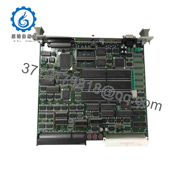
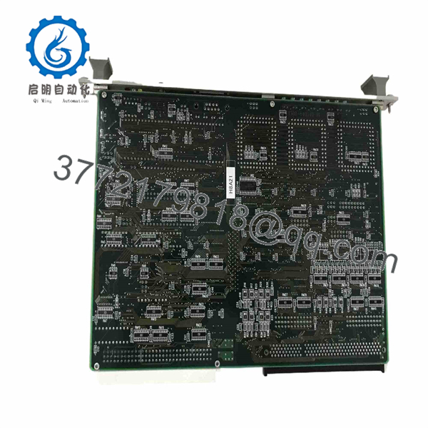
I would verify the PCB silkscreen, revision marking, connector layout, and equipment model against the original TEL documentation before installation.
Product Introduction
The TEL 1381-648241-15 is identified in semiconductor-equipment spare-parts records as a TVB-6003-1/EMIC EIMC control/interface board used in Tokyo Electron equipment. It belongs to the TVB-6003 family of machine-specific control electronics rather than a general-purpose PLC I/O platform.
For replacement work, the exact suffix matters. TEL spare-parts databases and aftermarket inventories separately identify 1381-648241-12, -14, and -15, so a visually similar TVB board should not be assumed interchangeable. Match the complete part number, PCB revision, connector arrangement, and tool configuration before ordering.
Installation & Configuration Guide
Stage 1: Pre-Installation Preparation — About 10–15 minutes
⚠️ Safety First: Place the TEL tool into its approved maintenance state. Follow the equipment-specific shutdown and LOTO procedure before accessing the control rack. Semiconductor equipment may contain multiple power domains that remain energized after the main disconnect is opened.
Tools Required:
- ESD wrist strap
- ESD-safe work surface
- Phillips screwdriver
- Digital multimeter
- Cable labels
- Smartphone/camera
- TEL equipment schematic or maintenance manual
Data Backup:
- Record the complete installed part number: 1381-648241-15.
- Record the board revision and any serial/date code.
- Photograph the front and rear of the board where accessible.
- Photograph every connected harness.
- Record connector locations and cable routing.
- Record all board LEDs before removal.
- Record active TEL equipment alarms.
- Confirm whether the existing board contains configuration data or machine-specific settings.
❗ Do not use 1381-648241-12 or 1381-648241-14 as an assumed replacement. They are separately cataloged TEL parts.
Stage 2: Removing the Old Board — About 5–10 minutes
- Shut down the TEL equipment using the approved maintenance procedure.
- Isolate the applicable power sources.
- Verify the relevant electrical rails are de-energized.
- Apply ESD protection.
- Photograph the complete board installation.
- Label each harness.
- Release connector locking mechanisms.
- Disconnect the harnesses without pulling on individual wires.
- Remove the board retaining hardware.
- Pull the PCB straight from the backplane connector.
- Inspect the board connector and backplane for bent pins, contamination, or mechanical damage.
⚠️ Do not force the board. A damaged backplane connector can create multiple downstream equipment faults.
Stage 3: Installing the New Board — About 5–10 minutes
- Confirm the replacement marking is TEL 1381-648241-15.
- Compare the PCB revision with the removed board.
- Compare connector locations and board geometry.
- Inspect the replacement for corrosion, contamination, cracked components, or rework marks.
- Align the PCB with the dedicated TEL rack slot.
- Insert the board straight and evenly.
- Secure the retaining hardware.
- Reconnect every harness according to the photographs and machine schematic.
- Confirm all connector locks are engaged.
- Check that no cable is pinched or under mechanical tension.
Configuration Clone — Critical:
This is not a generic PLC module where you should assume a standard configuration procedure. Verify:
- Board revision
- Connector/harness assignment
- Equipment slot
- Controller communication settings
- Machine-specific configuration
- Any stored calibration or control parameters
- Firmware/software compatibility
Self-Checklist:
- Exact -15 suffix verified
- Board revision verified
- Correct TEL rack slot confirmed
- All connectors matched
- Harnesses secured
- PCB retaining hardware installed
- ESD precautions maintained
Stage 4: Power-On & Functional Testing — About 10–20 minutes
- Perform a complete visual inspection.
- Check for loose connectors or possible shorts.
- Restore power according to the TEL maintenance procedure.
- Observe the board’s LEDs.
- Check the host controller for board-recognition faults.
- Check for new communication or I/O alarms.
- Verify the expected equipment-interface status.
- Execute the relevant maintenance-mode sequence.
- Verify connected sensors and actuators respond correctly.
- Run the applicable TEL equipment initialization sequence.
- Monitor for recurring alarms.
- Return the equipment to production only after the complete functional sequence passes.
⚠️ Do not diagnose the PCB in isolation. A board-level alarm can originate from the backplane, power supply, harness, controller, or a connected field device.
Technical Pitfall & Survival Guide
❗ 1. Confusing -15 With -12 or -14
This is the first thing I would check. The TEL 1381-648241 family contains several separately listed variants. Current spare-parts catalogs identify -12, -14, and -15 as distinct parts.
Match the complete suffix.
❗ 2. EIMC vs. EMIC Naming
You will see both EIMC and EMIC in aftermarket descriptions. For purchasing purposes, the safest identifier is the complete TEL part number 1381-648241-15, followed by the physical board marking.
❗ 3. Assuming Generic I/O Compatibility
Do not treat this as a standard Allen-Bradley, Siemens, or Mitsubishi I/O module. It is a TEL machine-specific PCB. Its connector mapping and software relationship are determined by the TEL equipment architecture.
❗ 4. Firmware / Configuration Mismatch
If the board powers up but the TEL controller reports an initialization or communication fault, check the board revision and configuration before replacing hardware again.
I’ve seen legacy semiconductor tools lose hours of production time because a replacement PCB was electrically functional but belonged to a different hardware revision.
❗ 5. Connector Damage
A slightly bent backplane contact can produce intermittent communication faults that disappear during visual inspection and return during machine operation.
Inspect the backplane before declaring the replacement defective.
1381-648241-15
1381-648241-1515
Frequently Asked Questions (FAQ)
What is TEL 1381-648241-15?
It is a Tokyo Electron TVB-6003-series EIMC/EMIC control/interface board used as a machine-specific PCB in TEL semiconductor equipment. A TEL spare-parts listing identifies the exact number as TVB-6003-1/EMIC.
Is 1381-648241-15 a PLC I/O module?
Not in the conventional industrial-automation sense. It is a TEL equipment-specific control/interface board. Do not substitute a generic PLC I/O card simply because the board handles similar signals.
Is 1381-648241-15 the same as 1381-648241-12?
No assumption should be made that they are interchangeable. Both appear in TEL spare-parts inventories as separate TVB6003-related boards. The -12 is identified in current listings as TVB6003-1/EIMC, while the -15 is listed as .
Can I use 1381-648241-14 instead?
I would not approve that substitution without the TEL equipment schematic or an OEM-approved cross-reference. The -14 is separately cataloged as a TVB6003 board, which is not sufficient evidence that its electrical or software configuration matches the -15.
Is TEL 1381-648241-15 obsolete?
It should be treated as a legacy semiconductor-equipment spare. Current availability is primarily through specialist TEL aftermarket and surplus suppliers rather than normal current-production distribution. TEL spare-parts inventories still list the part, including quantities in a used TEL lot.
Can I hot-swap this board?
Do not assume hot-swap capability. I found no sufficiently authoritative source establishing live replacement for 1381-648241-15 specifically. Unless the applicable TEL equipment manual explicitly permits powered removal/insertion for this slot, shut down and isolate the equipment before replacing it.
What should I verify before purchasing?
For a production-critical TEL spare, request:
- TEL 1381-648241-15 exact label
- PCB revision
- Clear photographs of both PCB sides
- Connector photographs
- TEL equipment/tool model
- Condition: New Original, New Surplus, or Refurbished
- Functional-test procedure
- Warranty period
This is particularly important because nearby 1381-648241-12 and -14 variants are actively listed in the aftermarket, and confusing the suffix can result in receiving the wrong board.



