
 WhatsApp: +86 16626708626
 Email:
  Phone: +86 16626708626
Description
Key Technical Specifications
| Parameter | Value |
|---|---|
| Manufacturer | Terasaki |
| Model | ERB-112 |
| Product Type | PC Board / PLC Add-On Board |
| Part Number | ERB-112 |
| Alternate Part Number | K/751/3-002A |
| Indicators | Dual LED indicators |
| Listed Weight | 0.15 lb |
| Manufacturer Status | Discontinued |
| Application Category | PLCs / Machine Control |
| Mounting / Interface | Verify against the existing Terasaki assembly before replacement |
| Firmware | Not documented in the available sources |
| Electrical Ratings | Not documented in the available sources |
Available distributor records identify ERB-112 as a Terasaki PC board/add-on board rather than providing a complete electrical specification sheet. The documented information includes dual LED indicators, a 0.15 lb listed weight, and alternate part number K/751/3-002A.
A separate listing identifies an ERB-112 PCB variant as K/751/3-002B, so the suffix must be checked carefully against the physical board before ordering.
Product Introduction
The Terasaki ERB-112 is a discontinued PLC PC board/add-on board used in Terasaki industrial control equipment. Available component records identify dual LED indicators and list K/751/3-002A as an alternate part number.
For replacement work, the exact board marking matters. Do not substitute a visually similar Terasaki PCB solely from the ERB-112 designation; verify the complete part number, revision, connector arrangement, and installed-system documentation first.
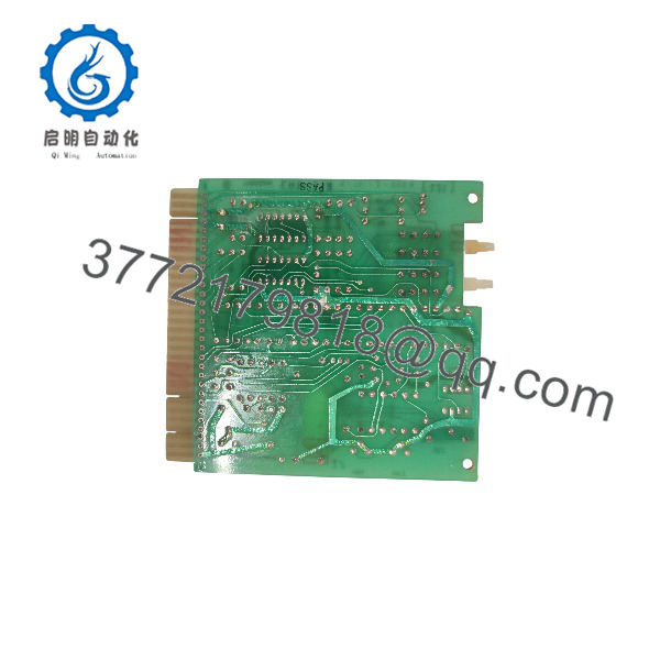
ERB-112
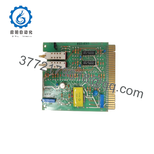
ERB-112
Installation & Configuration Guide
Stage 1: Pre-Installation Preparation — Approximately 5–10 Minutes
⚠️ Safety First: Put the controlled equipment into a documented safe state and follow the site’s lockout/tagout procedure before opening the control cabinet. Do not assume this PCB is safe to remove under power.
Tools Required:
- ESD wrist strap
- Appropriate screwdriver
- Digital multimeter
- Wire/connector identification labels
- Smartphone or camera for configuration photographs
Before removing the existing board:
- Record the complete marking on the installed PCB.
- Photograph both sides of the board if accessible.
- Photograph all connectors, wiring, jumpers, switches, and LED positions.
- Record any revision, serial, or manufacturing markings.
- Retain the original board until the replacement has been fully commissioned.
⚠️ Do not rely on “” alone. Available records show different suffix/part-number references, including K/751/3-002A and K/751/3-002B.
Stage 2: Removing the Old Module — Approximately 5 Minutes
- Confirm the equipment is de-energized according to the site’s isolation procedure.
- Remove the applicable protective cover or access panel.
- Identify every connector before disconnecting it.
- Do not pull on wires or force PCB connectors.
- Release the board’s mechanical retaining hardware.
- Remove the PCB straight and carefully to avoid connector or backplane damage.
- Inspect the mating connectors for bent contacts, contamination, corrosion, or mechanical damage.
Keep the removed available for direct comparison during installation.
Stage 3: Installing the Replacement — Approximately 5–10 Minutes
- Put on an ESD wrist strap and use appropriate ESD handling practices.
- Verify the complete replacement part number against the removed PCB.
- Compare connector locations and board markings side by side.
- Reproduce any documented jumper or switch settings exactly.
- Install the board without excessive force.
- Reconnect each connector according to the photographs and original wiring documentation.
- Confirm that no connector is partially seated.
- Reinstall retaining hardware and covers as required.
Self-Checklist:
- Complete part number verified
- PCB revision checked
- Connector positions match
- Jumpers/switches checked
- Wiring/connector identification confirmed
- PCB fully seated
- Retaining hardware secured
Stage 4: Power-On & Testing — Approximately 10 Minutes
- Perform a final visual inspection before energizing the equipment.
- Verify that no loose hardware or foreign material remains inside the cabinet.
- Restore power according to the site’s approved startup procedure.
- Observe the ‘s dual LED indicators and compare their behavior with the original board and available Terasaki documentation.
- Check the host controller/system for diagnostic or communication faults.
- Execute the applicable machine or control-system functional test.
- Confirm that the system returns to its normal operating state.
⚠️ Do not assign LED colors, electrical meanings, or diagnostic codes without the applicable Terasaki documentation. The available distributor records confirm dual LED indicators but do not provide a reliable LED status table.
Frequently Asked Questions (FAQ)
Q: Is the Terasaki still manufactured?
The available distributor documentation identifies the as discontinued by the manufacturer. Replacement sourcing therefore generally depends on remaining inventory, unused surplus stock, or refurbished units.
Q: What is the alternate part number for ?
One established distributor record lists Terasaki K/751/3-002A as an alternate part number for .
Q: I found a K/751/3-002B. Is it automatically interchangeable with ?
No. A separate listing identifies K/751/3-002B as an PCB variant, but the available sources do not establish complete interchangeability between the A and B variants. Verify the board revision, connectors, and system documentation before substitution.
Q: Can I hot-swap the ?
Do not assume that it is hot-swappable. The available documentation does not establish a hot-swap capability. Unless the applicable Terasaki system manual explicitly permits energized replacement, isolate power before removing the PCB.
Q: Is the a complete PLC CPU?
The available distributor records classify it as a PC Board / PLC Add-On Board and an industrial computer accessory. They do not document it as a standalone PLC CPU.
Q: How should I verify a replacement before purchasing?
Compare the complete part number, PCB markings, revision information, connector arrangement, physical layout, and existing system documentation. This is particularly important because marketplace records show more than one K/751/3-002 variant associated with .
Q: Is a listing marked “New” necessarily factory-sealed Terasaki stock?
Not necessarily. Marketplace condition terminology can distinguish factory-new, never-used original packaging, repackaged unused stock, and refurbished equipment. Confirm the actual condition, original packaging, traceability, and test documentation with the supplier before purchase.



